
User's Manual
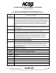
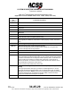
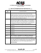
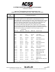
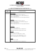
Table Of Contents
- T3CAS_Section_5
- 5 Adjustment/Test
- 1. General
- 2. Equipment
- 3. Initial Harness Checkout (New Installations Only)
- 4. System Self-Tests
- 5. Return-to-Service Test
- 6. Operational Software Loading Using an ARINC 615A Portable Data Loader or Compact Flash Card
- 7. Downloading Information from the TP3PCAS Using a CF Card
- 1. Obtain a New or Blank Compact Flash (CF) card.
- 2. Copy to the New or Blank CF card the appropriate ‘Header File’
- a) Header files are files copied to the New or Blank CF card that will instruct the computer unit what is desired to be downloaded.
- b) Header files needed to download Maintenance Data, Event Data and CRC Part Numbers can be obtained from ACSS Customer Services at +1-623-445-7070 or crc.acss@l-3com.com.
- 3. For downloading Maintenance Data, Event Data or CRC Part Numbers the aircraft does not need to be in an on-ground configuration.
- 4. Apply power to the computer unit.
- 5. Insert the CF card.
- 6. For ACSS part numbers 9005000-10000, -10101, -10202, and -10204 the DATA STATUS LED will UblinkU green once; this indicates the unit recognized that a CF card was inserted.
- 7. For ACSS part numbers 9005000-11203, -11801 and -55801 the DATA STATUS LED will UblinkU green while reading the header file and performing the action defined in the header file.
- 8. Flight Data Recording
- 1. T3CAS part numbers 9005000-10000, -10101, -10202, and -10204 only support FAT16 CF card formatting. T3CAS part numbers 9005000-11203, -11801 and -55801 support both FAT16 and FAT32 CF card formatting.
- B. Flight Data
- 1. Obtain a New or Blank CF Card.
- 2. Copy to the New or Blank CF Card the Appropriate Header File.
- 3. Header files are files copied to the New or Blank CF card that will instruct the computer unit what is desired to be downloaded.
- 4. For Flight Data Recording, the aircraft does not need to be in an on-ground configuration.
- 5. Apply power to the computer unit.
- 6. Insert the CF card.
- B. Flight Data
- 9. Downloaded Maintenance Data, Event Data And Flight Data May Be Sent To ACSS Customer Services For Analysis
- 5 Adjustment/Test
- T3CAS_Section_6
- T3CAS_Section_7
- 7 Maintenance Practices
- 1. General
- 2. Equipment and Materials
- 3. Procedure for the TP3PCAS Computer Unit
- 4. Procedure for the APM (Not applicable for part numbers 9005000-10000, -10101, -10202, -10204, or -11203)
- 5. Procedure for the Directional Antenna
- 6. Procedure for the Omnidirectional Antenna (Applicable to part numbers 9005000-11203, -11801 and -55801)
- 7. Procedure for the Control Panel
- 8. Procedure for the VSI/TRA Display
- 9. Instructions for Continued Airworthiness, FAR Part 25.1529
- 7 Maintenance Practices
- T3CAS_Section_8
- T3CAS_Section_9
- T3CAS_Section_10
- T3CAS_Appendix_A

SYSTEM DESCRIPTION AND INSTALLATION MANUAL
T
3
CAS/Part No.9005000
Table 4-1: T
3
CAS Computer Unit Interface Description (cont)
(Applicable to Part No. 9005000-10000, -10101, -10202, -10204, and -11203)
Connector
Pin
Designation
Functional Description
RMP-7E
TA Display No.1 Status Discrete Input (NO)
Two display status ground/open discrete inputs (Note 1) are provided by the
T
3
CAS computer unit at RMP-7E (TA Display No.1) and RMP-7J (TA Display
No.2). If a display provides a ground on either of these inputs, it is interpreted by
TCAS to mean the display associated with that input is operating normally and is
capable of displaying the TA information, and that its data bus is active. An open
indicates the inability of the display to present advisories or indicates its data bus is
inactive.
RMP-7F
Reserved Discrete Input (NO)
RMP-7G, 7H
ARINC 429 TA/RA Display No.2 Output: [RMP-7G (A), RMP-7H (B)]
See RMP-7C and -7D.
RMP-7J
TA Display No.2 Status Discrete Input (NO)
See RMP-7E.
RMP-7K
Reserved Discrete Input (NO)
RMP-8A, 8B
Reserved
RMP-8C, 8D
ARINC 429 ADS-B No.1 Input (DMC #1/3): [RMP-8C (A), RMP-8D (B)]
TA/RA Display Control A429 high-speed Input #1/3.
RMP-8E, 8F
ARINC 429 Bus Input: [RMP-8E (A), RMP-8F (B)]
General Purpose low-speed A429 Input #1, may be used as an MCDU #1 input for
some installations.
RMP-8G, 8H
ARINC 429 DMC #2 Bus Input: [RMP-8G (A), RMP-8H (B)]
TA/RA Display Control A429 high-speed Input #2.
RMP-8J, 8K
ARINC 429 Bus Input: [RMP-8J (A), RMP-8K (B)]
General Purpose low-speed A429 Input #2, may be used as an MCDU #2 input for
some installations.
RMP-9A, 9B
ARINC 429 ADLP Comm C Output: [RMP-9A (A), RMP-9B (B)]
These pins serve as the input interface to the transponder function ADLP Comm C
protocol.
RMP-9C, 9D
Reserved for ARINC 735B Data Bus Output.
RMP-9E, 9F
Reserved for ARINC 735B Data Bus Output.
RMP-9G, 9H
ARINC 429 Bus Output: [RMP-9G (A), RMP-9H (B)]
CD General Purpose A429 Output #1, may be used for MCDU #1 and #2 for some
installations.
RMP-9J, 9K
Reserved ARINC 429 Bus Output
4-16
04 Nov 2014
34-45-29
Pub. No. 8600200-001, Revision 004
Use or disclosure of information on this page is subject to the restrictions in the proprietary notice of this document.