
User's Manual
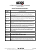
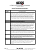
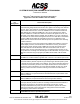
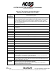
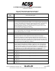
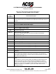
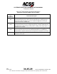
Table Of Contents
- T3CAS_Section_5
- 5 Adjustment/Test
- 1. General
- 2. Equipment
- 3. Initial Harness Checkout (New Installations Only)
- 4. System Self-Tests
- 5. Return-to-Service Test
- 6. Operational Software Loading Using an ARINC 615A Portable Data Loader or Compact Flash Card
- 7. Downloading Information from the TP3PCAS Using a CF Card
- 1. Obtain a New or Blank Compact Flash (CF) card.
- 2. Copy to the New or Blank CF card the appropriate ‘Header File’
- a) Header files are files copied to the New or Blank CF card that will instruct the computer unit what is desired to be downloaded.
- b) Header files needed to download Maintenance Data, Event Data and CRC Part Numbers can be obtained from ACSS Customer Services at +1-623-445-7070 or crc.acss@l-3com.com.
- 3. For downloading Maintenance Data, Event Data or CRC Part Numbers the aircraft does not need to be in an on-ground configuration.
- 4. Apply power to the computer unit.
- 5. Insert the CF card.
- 6. For ACSS part numbers 9005000-10000, -10101, -10202, and -10204 the DATA STATUS LED will UblinkU green once; this indicates the unit recognized that a CF card was inserted.
- 7. For ACSS part numbers 9005000-11203, -11801 and -55801 the DATA STATUS LED will UblinkU green while reading the header file and performing the action defined in the header file.
- 8. Flight Data Recording
- 1. T3CAS part numbers 9005000-10000, -10101, -10202, and -10204 only support FAT16 CF card formatting. T3CAS part numbers 9005000-11203, -11801 and -55801 support both FAT16 and FAT32 CF card formatting.
- B. Flight Data
- 1. Obtain a New or Blank CF Card.
- 2. Copy to the New or Blank CF Card the Appropriate Header File.
- 3. Header files are files copied to the New or Blank CF card that will instruct the computer unit what is desired to be downloaded.
- 4. For Flight Data Recording, the aircraft does not need to be in an on-ground configuration.
- 5. Apply power to the computer unit.
- 6. Insert the CF card.
- B. Flight Data
- 9. Downloaded Maintenance Data, Event Data And Flight Data May Be Sent To ACSS Customer Services For Analysis
- 5 Adjustment/Test
- T3CAS_Section_6
- T3CAS_Section_7
- 7 Maintenance Practices
- 1. General
- 2. Equipment and Materials
- 3. Procedure for the TP3PCAS Computer Unit
- 4. Procedure for the APM (Not applicable for part numbers 9005000-10000, -10101, -10202, -10204, or -11203)
- 5. Procedure for the Directional Antenna
- 6. Procedure for the Omnidirectional Antenna (Applicable to part numbers 9005000-11203, -11801 and -55801)
- 7. Procedure for the Control Panel
- 8. Procedure for the VSI/TRA Display
- 9. Instructions for Continued Airworthiness, FAR Part 25.1529
- 7 Maintenance Practices
- T3CAS_Section_8
- T3CAS_Section_9
- T3CAS_Section_10
- T3CAS_Appendix_A

SYSTEM DESCRIPTION AND INSTALLATION MANUAL
T
3
CAS/Part No.9005000
Table 4-2: T
3
CAS Computer Unit Interface Description
(Applicable to Part No. 9005000-11801 and -55801)
Connector
Pin
Designation
Functional Description
RMP-5H
Reserved: No Connection
RMP-5J
Reserved: No Connection
RMP-5K
Air Ground Discrete Input (NO): (Weight-On-Wheels)
This ground/open-type discrete input (Note 1) to the T
3
CAS computer unit indicates
the status of the Air/Ground or Weight-On-Wheels (WOW) switch. TCAS filters this
input to make sure it remains in a steady state a minimum of 4 sec before an
Air/Ground transition is recorded. An open indicates the aircraft is airborne and a
ground indicates the aircraft is on the ground.
Inputs should be diode isolated from each other.
RMP-6A, 6B
ARINC 429 FMC – GENBUS #1 (NAV Modes) Input: [RMP-6A (A), RMP-6B (B)]
This Low-Speed ARINC 429 (12.5k bits/s) input provides aircraft gross weight,
selected altitude, position, etc. to T
3
CAS.
RMP-6C
Reserved: No Connection
RMP-6D
Performance Limit Discrete Input (NO)
This input provides the T
3
CAS computer unit with an input from the Flight
Management Computer (or equivalent) which indicates when the aircraft cannot
achieve a 1500 FPM (457.2 m/min) climb rate. When this input is ground, the climb
rate is not limited and no action is needed by the T
3
CAS computer unit. When this
input is open, the climb rate is limited when the aircraft is above the value set by the
altitude limit program pins (RMP-6E thru RMP-6J).
RMP-6E
2000 ft (609.6 m) Altitude Limit Program Pin (NO)
This pin, along with pins RMP-6F thru RMP-6J, select the “can’t climb” altitude in
2,000-ft (609.6-m) increments up to 62,000 ft (18897.6 m). This is the altitude the
aircraft is not able to achieve a 0.25-g vertical acceleration to a 1500-FPM (457.2-
m) climb rate for an altitude gain of 750 ft (28.6 m) above a certain altitude under all
circumstances. The “can’t climb” altitude is selected by connecting jumper wires
from altitude limit program pins to the program common pin (RMP-6K).
RMP-6F
4000 ft (1219.2 m) Altitude Limit Program Pin (NO)
See RMP-6E.
RMP-6G
8000 ft (2438.4 m) Altitude Limit Program Pin (NO)
See RMP-6E.
RMP-6H
16000 ft (4876.8 m) Altitude Limit Program Pin (NO)
See RMP-6E.
RMP-6J
32000 ft (9753.6 m) Altitude Limit Program Pin (NO)
See RMP-6E.
RMP-6K
Program Common
See RMP-6E.
Pub. No. 8600200-001, Revision 004
34-45-29
4-49
04 Nov 2014
Use or disclosure of information on this page is subject to the restrictions in the proprietary notice of this document.