
User's Manual
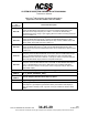
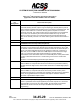
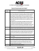
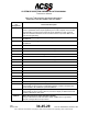
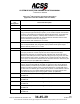
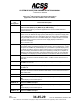
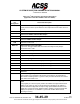
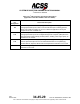
Table Of Contents
- T3CAS_Section_5
- 5 Adjustment/Test
- 1. General
- 2. Equipment
- 3. Initial Harness Checkout (New Installations Only)
- 4. System Self-Tests
- 5. Return-to-Service Test
- 6. Operational Software Loading Using an ARINC 615A Portable Data Loader or Compact Flash Card
- 7. Downloading Information from the TP3PCAS Using a CF Card
- 1. Obtain a New or Blank Compact Flash (CF) card.
- 2. Copy to the New or Blank CF card the appropriate ‘Header File’
- a) Header files are files copied to the New or Blank CF card that will instruct the computer unit what is desired to be downloaded.
- b) Header files needed to download Maintenance Data, Event Data and CRC Part Numbers can be obtained from ACSS Customer Services at +1-623-445-7070 or crc.acss@l-3com.com.
- 3. For downloading Maintenance Data, Event Data or CRC Part Numbers the aircraft does not need to be in an on-ground configuration.
- 4. Apply power to the computer unit.
- 5. Insert the CF card.
- 6. For ACSS part numbers 9005000-10000, -10101, -10202, and -10204 the DATA STATUS LED will UblinkU green once; this indicates the unit recognized that a CF card was inserted.
- 7. For ACSS part numbers 9005000-11203, -11801 and -55801 the DATA STATUS LED will UblinkU green while reading the header file and performing the action defined in the header file.
- 8. Flight Data Recording
- 1. T3CAS part numbers 9005000-10000, -10101, -10202, and -10204 only support FAT16 CF card formatting. T3CAS part numbers 9005000-11203, -11801 and -55801 support both FAT16 and FAT32 CF card formatting.
- B. Flight Data
- 1. Obtain a New or Blank CF Card.
- 2. Copy to the New or Blank CF Card the Appropriate Header File.
- 3. Header files are files copied to the New or Blank CF card that will instruct the computer unit what is desired to be downloaded.
- 4. For Flight Data Recording, the aircraft does not need to be in an on-ground configuration.
- 5. Apply power to the computer unit.
- 6. Insert the CF card.
- B. Flight Data
- 9. Downloaded Maintenance Data, Event Data And Flight Data May Be Sent To ACSS Customer Services For Analysis
- 5 Adjustment/Test
- T3CAS_Section_6
- T3CAS_Section_7
- 7 Maintenance Practices
- 1. General
- 2. Equipment and Materials
- 3. Procedure for the TP3PCAS Computer Unit
- 4. Procedure for the APM (Not applicable for part numbers 9005000-10000, -10101, -10202, -10204, or -11203)
- 5. Procedure for the Directional Antenna
- 6. Procedure for the Omnidirectional Antenna (Applicable to part numbers 9005000-11203, -11801 and -55801)
- 7. Procedure for the Control Panel
- 8. Procedure for the VSI/TRA Display
- 9. Instructions for Continued Airworthiness, FAR Part 25.1529
- 7 Maintenance Practices
- T3CAS_Section_8
- T3CAS_Section_9
- T3CAS_Section_10
- T3CAS_Appendix_A

SYSTEM DESCRIPTION AND INSTALLATION MANUAL
T
3
CAS/Part No.9005000
Table 4-2: T
3
CAS Computer Unit Interface Description
(Applicable to Part No. 9005000-11801 and -55801)
Connector
Pin
Designation
Functional Description
RMP-2H, 2J
Radio Altimeter No.1 ARINC 552/Analog Input: (RMP-2H [HI], RMP-2J [LO])
Normal aircraft configurations include either two digital or two analog radio altimeter
sources. The T
3
CAS computer unit attempts to establish which type is present in
order to obtain data from one of the two available sources. TCAS first checks the
radio altimeter No.1 valid flag at RMP-2K. If No.1 is not valid then No.2 valid is
checked at RBP-3C. If neither are valid then TCAS checks digital source No.1 for
valid data on the ARINC 429 bus at RMP-13H and RMP-13J. If none of the above
are valid then the TCAS checks the digital source No.2 for valid data on the ARINC
429 bus at RBP-3D and RBP-3E and digital source No.3 for valid data on the
ARINC 429 bus at RTP-5A and RTP-5B. This process is repeated until a valid flag
or data is detected.
Until a valid source is found, the TCAS function inhibits all surveillance, CAS, and
TA/RA display functions, records failures in maintenance memory, and sets the
TCAS system status discrete output at RMP-13K to invalid. The TCAS function
uses radio altitude to inhibit advisories and aural annunciation when in close
proximity to the ground. This analog input No.1, as well as analog input No.2, can
accept data as a dc voltage from several types of radio altimeters. The type of radio
altimeter is selected using the program pins RMP-12B and RMP-12D thru RMP-
12F.
RMP-2K
Radio Altimeter No.1 Valid Input (PO)
See RMP-2H. A valid condition is greater than +18.5 V dc. An invalid is open circuit.
RMP-3A
Corrective Visual Advisory Discrete Output (NO)
The visual advisory discrete outputs are ground/open-type discretes (Note 3) used
to operate the annunciator lights on the displays. This output is activated whenever
a corrective aural advisory is issued. The output remains active for the duration of
the advisory unless cancelled by the cancel discrete at RMP-3D. Only one visual
advisory is active at a time. The active state is ground and the inactive state is
open.
RMP-3B
Preventive Visual Advisory Discrete Output (NO)
Same as RMP-3A, except this discrete is activated whenever a preventative aural
advisory is issued.
RMP-3C
Traffic Visual Advisory Discrete Output (NO)
Same as RMP-3A, except this discrete is active during a traffic advisory.
RMP-3D
Cancel Discrete Input (NO)
This input discrete provides a means of canceling TCAS aural and visual alerts. It
should be connected to a cancel button (momentary ground type), if used.
Groundprox/Windshear has priority over the cancel button. Open is the inactive
state and a momentary ground (less than 50 ohms) produces the active state,
canceling any active aural or visual alert.
RMP-3E
TCAS/ADS-B Discrete Output #4 (Lamp Driver)
Pub. No. 8600200-001, Revision 004
34-45-29
4-47
04 Nov 2014
Use or disclosure of information on this page is subject to the restrictions in the proprietary notice of this document.