
User's Manual
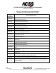
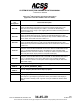
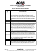
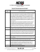
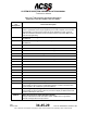
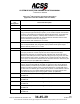
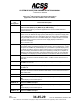
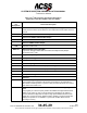
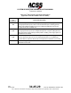
Table Of Contents
- T3CAS_Section_5
- 5 Adjustment/Test
- 1. General
- 2. Equipment
- 3. Initial Harness Checkout (New Installations Only)
- 4. System Self-Tests
- 5. Return-to-Service Test
- 6. Operational Software Loading Using an ARINC 615A Portable Data Loader or Compact Flash Card
- 7. Downloading Information from the TP3PCAS Using a CF Card
- 1. Obtain a New or Blank Compact Flash (CF) card.
- 2. Copy to the New or Blank CF card the appropriate ‘Header File’
- a) Header files are files copied to the New or Blank CF card that will instruct the computer unit what is desired to be downloaded.
- b) Header files needed to download Maintenance Data, Event Data and CRC Part Numbers can be obtained from ACSS Customer Services at +1-623-445-7070 or crc.acss@l-3com.com.
- 3. For downloading Maintenance Data, Event Data or CRC Part Numbers the aircraft does not need to be in an on-ground configuration.
- 4. Apply power to the computer unit.
- 5. Insert the CF card.
- 6. For ACSS part numbers 9005000-10000, -10101, -10202, and -10204 the DATA STATUS LED will UblinkU green once; this indicates the unit recognized that a CF card was inserted.
- 7. For ACSS part numbers 9005000-11203, -11801 and -55801 the DATA STATUS LED will UblinkU green while reading the header file and performing the action defined in the header file.
- 8. Flight Data Recording
- 1. T3CAS part numbers 9005000-10000, -10101, -10202, and -10204 only support FAT16 CF card formatting. T3CAS part numbers 9005000-11203, -11801 and -55801 support both FAT16 and FAT32 CF card formatting.
- B. Flight Data
- 1. Obtain a New or Blank CF Card.
- 2. Copy to the New or Blank CF Card the Appropriate Header File.
- 3. Header files are files copied to the New or Blank CF card that will instruct the computer unit what is desired to be downloaded.
- 4. For Flight Data Recording, the aircraft does not need to be in an on-ground configuration.
- 5. Apply power to the computer unit.
- 6. Insert the CF card.
- B. Flight Data
- 9. Downloaded Maintenance Data, Event Data And Flight Data May Be Sent To ACSS Customer Services For Analysis
- 5 Adjustment/Test
- T3CAS_Section_6
- T3CAS_Section_7
- 7 Maintenance Practices
- 1. General
- 2. Equipment and Materials
- 3. Procedure for the TP3PCAS Computer Unit
- 4. Procedure for the APM (Not applicable for part numbers 9005000-10000, -10101, -10202, -10204, or -11203)
- 5. Procedure for the Directional Antenna
- 6. Procedure for the Omnidirectional Antenna (Applicable to part numbers 9005000-11203, -11801 and -55801)
- 7. Procedure for the Control Panel
- 8. Procedure for the VSI/TRA Display
- 9. Instructions for Continued Airworthiness, FAR Part 25.1529
- 7 Maintenance Practices
- T3CAS_Section_8
- T3CAS_Section_9
- T3CAS_Section_10
- T3CAS_Appendix_A

SYSTEM DESCRIPTION AND INSTALLATION MANUAL
T
3
CAS/Part No.9005000
Table 4-2: T
3
CAS Computer Unit Interface Description
(Applicable to Part No. 9005000-11801 and -55801)
Connector
Pin
Designation
Functional Description
RTP-13H
Programmable/Strobed Ground Discrete Output
Spare /TAWS/XPDR 500 mA
RTP-13J
Ground Discrete Output
Terrain Display Select #1 500 mA
RTP-13K
Programmable/Strobed Ground Discrete Output
Spare /TAWS/XPDR 500 mA
RTP-14A
Ground Discrete Output
Terrain Display Select #2 500 mA
RTP-14B
Ground Discrete Monitor Output
GPWS Monitor 250 mA
RTP-14C
Ground Discrete Monitor Output
Terrain Not Available Monitor 250 mA
RTP-14D
Ground Discrete Monitor Output
Terrain Monitor 250 mA
RTP-14E
Discrete Input (Gnd/Open)
XPDR Functional Test
RTP-14F
Discrete Input (Gnd/Open), Latch
Standby/ON
RTP-14G
Discrete Input (Gnd/Open)
XPDR Mode S Address Bit A23
RTP-14H
Discrete Input (Gnd/Open)
XPDR Mode S Address Bit A24
RTP-14J
Ground Discrete Output
Spare
RTP-14K
Discrete Output 500 mA
XPDR Fail #2
RTP-15A
Discrete Output 5 V dc / 100 mA
XPDR Fail #1
RTP-15B,
15C
ARINC 429 TCAS Output
This bus outputs Dataloader or ADLP COMM A data.
RTP-15D
APM Power
+12 V dc power source for the Airplane Personality Module. Connect to APM J1-7.
RTP-15E
APM Return
This is the Ground return for +12 V dc APM power source. Connect to APM J1-8.
See pin RTP-15D
4-44
04 Nov 2014
34-45-29
Pub. No. 8600200-001, Revision 004
Use or disclosure of information on this page is subject to the restrictions in the proprietary notice of this document.