
User's Manual
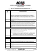
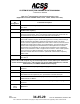
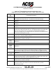
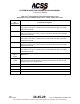
Table Of Contents
- T3CAS_Section_5
- 5 Adjustment/Test
- 1. General
- 2. Equipment
- 3. Initial Harness Checkout (New Installations Only)
- 4. System Self-Tests
- 5. Return-to-Service Test
- 6. Operational Software Loading Using an ARINC 615A Portable Data Loader or Compact Flash Card
- 7. Downloading Information from the TP3PCAS Using a CF Card
- 1. Obtain a New or Blank Compact Flash (CF) card.
- 2. Copy to the New or Blank CF card the appropriate ‘Header File’
- a) Header files are files copied to the New or Blank CF card that will instruct the computer unit what is desired to be downloaded.
- b) Header files needed to download Maintenance Data, Event Data and CRC Part Numbers can be obtained from ACSS Customer Services at +1-623-445-7070 or crc.acss@l-3com.com.
- 3. For downloading Maintenance Data, Event Data or CRC Part Numbers the aircraft does not need to be in an on-ground configuration.
- 4. Apply power to the computer unit.
- 5. Insert the CF card.
- 6. For ACSS part numbers 9005000-10000, -10101, -10202, and -10204 the DATA STATUS LED will UblinkU green once; this indicates the unit recognized that a CF card was inserted.
- 7. For ACSS part numbers 9005000-11203, -11801 and -55801 the DATA STATUS LED will UblinkU green while reading the header file and performing the action defined in the header file.
- 8. Flight Data Recording
- 1. T3CAS part numbers 9005000-10000, -10101, -10202, and -10204 only support FAT16 CF card formatting. T3CAS part numbers 9005000-11203, -11801 and -55801 support both FAT16 and FAT32 CF card formatting.
- B. Flight Data
- 1. Obtain a New or Blank CF Card.
- 2. Copy to the New or Blank CF Card the Appropriate Header File.
- 3. Header files are files copied to the New or Blank CF card that will instruct the computer unit what is desired to be downloaded.
- 4. For Flight Data Recording, the aircraft does not need to be in an on-ground configuration.
- 5. Apply power to the computer unit.
- 6. Insert the CF card.
- B. Flight Data
- 9. Downloaded Maintenance Data, Event Data And Flight Data May Be Sent To ACSS Customer Services For Analysis
- 5 Adjustment/Test
- T3CAS_Section_6
- T3CAS_Section_7
- 7 Maintenance Practices
- 1. General
- 2. Equipment and Materials
- 3. Procedure for the TP3PCAS Computer Unit
- 4. Procedure for the APM (Not applicable for part numbers 9005000-10000, -10101, -10202, -10204, or -11203)
- 5. Procedure for the Directional Antenna
- 6. Procedure for the Omnidirectional Antenna (Applicable to part numbers 9005000-11203, -11801 and -55801)
- 7. Procedure for the Control Panel
- 8. Procedure for the VSI/TRA Display
- 9. Instructions for Continued Airworthiness, FAR Part 25.1529
- 7 Maintenance Practices
- T3CAS_Section_8
- T3CAS_Section_9
- T3CAS_Section_10
- T3CAS_Appendix_A

SYSTEM DESCRIPTION AND INSTALLATION MANUAL
T
3
CAS/Part No.9005000
Table 4-2: T
3
CAS Computer Unit Interface Description
(Applicable to Part No. 9005000-11801 and -55801)
Connector
Pin
Designation
Functional Description
T
3
CAS Computer Unit Right Top Plug (RTP)
RTP-1A, 1B
ARINC 453 Terrain Display Output No.1: (RTP-1A [A], RTP-1B [B])
T
3
CAS output number 1 to the terrain awareness display.
RTP-1C, 1D
ARINC 429 Input: Spare
RTP-1E, 1F
ARINC 453 Terrain Display Output No.2: (RTP-1E [A], RTP-1F [B])
T
3
CAS output number 2 to the terrain awareness display.
RTP-1G, 1H
ARINC 429 Input: AFMC – EFIS #2 [RTP-1G (A), RTP-1H (B)]
This high-speed 429 input from the Flight Management Computer (FMC) Electronic
Flight Instrument System (EFIS) provides position, heading, track angle, speed,
etc. information to the T
3
CAS.
RTP-1J, 1K
ARINC 429 Input: ADIRU #2 (Right) / ADR [RTP-1J (A), RTP-1K (B)]
This low-speed 429 input from the Air Data/Inertial Reference Unit (ADIRU) #2
provides altitude, airspeed, altitude rate and temperature information to the T
3
CAS.
RTP-2A, 2B
ARINC 429 Input: Spare
RTP-2C, 2D
ARINC 429 Air Data/Inertial Reference Unit (ADIRU) #2 (Right), Inertial
Reference Part (IRS) Input: [RTP-2C (A), RTP-2D (B)]
This high-speed input is provided for applications to receive Inertial Reference
System information.
RTP-2E, 2F
Instrument Landing System #2 (Right)
This low-speed bus inputs all signals associated with the instrument landing system
to the T
3
CAS.
RTP-2G
Discrete Input (Gnd/Open)
XPDR Mode S Address Bit A1 (MSB). Refer to Note 5 following the table.
RTP-2H
Discrete Input (Gnd/Open)
XPDR Mode S Address Bit A2.
RTP-2J
Discrete Input (Gnd/Open)
XPDR Mode S Address Bit A3.
RTP-2K
Discrete Input (Gnd/Open)
XPDR Mode S Address Bit A4.
RTP-3A, 3B
Instrument Landing System #1 (Left)
This low-speed bus inputs all signals associated with the instrument landing system
to the T
3
CAS.
RTP-3C, 3D
ARINC 429 Input: Spare
RTP-3E, 3F
ARINC 429 FMC – GENBUS #2 (NAV Modes) Input: [RTP-3E (A), RTP-3F (B)]
This Low-Speed ARINC 429 (12.5k bits/s) input provides aircraft gross weight,
selected altitude, position, etc. to T
3
CAS.
4-38
04 Nov 2014
34-45-29
Pub. No. 8600200-001, Revision 004
Use or disclosure of information on this page is subject to the restrictions in the proprietary notice of this document.