
User's Manual
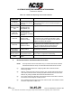
Table Of Contents
- T3CAS_Section_5
- 5 Adjustment/Test
- 1. General
- 2. Equipment
- 3. Initial Harness Checkout (New Installations Only)
- 4. System Self-Tests
- 5. Return-to-Service Test
- 6. Operational Software Loading Using an ARINC 615A Portable Data Loader or Compact Flash Card
- 7. Downloading Information from the TP3PCAS Using a CF Card
- 1. Obtain a New or Blank Compact Flash (CF) card.
- 2. Copy to the New or Blank CF card the appropriate ‘Header File’
- a) Header files are files copied to the New or Blank CF card that will instruct the computer unit what is desired to be downloaded.
- b) Header files needed to download Maintenance Data, Event Data and CRC Part Numbers can be obtained from ACSS Customer Services at +1-623-445-7070 or crc.acss@l-3com.com.
- 3. For downloading Maintenance Data, Event Data or CRC Part Numbers the aircraft does not need to be in an on-ground configuration.
- 4. Apply power to the computer unit.
- 5. Insert the CF card.
- 6. For ACSS part numbers 9005000-10000, -10101, -10202, and -10204 the DATA STATUS LED will UblinkU green once; this indicates the unit recognized that a CF card was inserted.
- 7. For ACSS part numbers 9005000-11203, -11801 and -55801 the DATA STATUS LED will UblinkU green while reading the header file and performing the action defined in the header file.
- 8. Flight Data Recording
- 1. T3CAS part numbers 9005000-10000, -10101, -10202, and -10204 only support FAT16 CF card formatting. T3CAS part numbers 9005000-11203, -11801 and -55801 support both FAT16 and FAT32 CF card formatting.
- B. Flight Data
- 1. Obtain a New or Blank CF Card.
- 2. Copy to the New or Blank CF Card the Appropriate Header File.
- 3. Header files are files copied to the New or Blank CF card that will instruct the computer unit what is desired to be downloaded.
- 4. For Flight Data Recording, the aircraft does not need to be in an on-ground configuration.
- 5. Apply power to the computer unit.
- 6. Insert the CF card.
- B. Flight Data
- 9. Downloaded Maintenance Data, Event Data And Flight Data May Be Sent To ACSS Customer Services For Analysis
- 5 Adjustment/Test
- T3CAS_Section_6
- T3CAS_Section_7
- 7 Maintenance Practices
- 1. General
- 2. Equipment and Materials
- 3. Procedure for the TP3PCAS Computer Unit
- 4. Procedure for the APM (Not applicable for part numbers 9005000-10000, -10101, -10202, -10204, or -11203)
- 5. Procedure for the Directional Antenna
- 6. Procedure for the Omnidirectional Antenna (Applicable to part numbers 9005000-11203, -11801 and -55801)
- 7. Procedure for the Control Panel
- 8. Procedure for the VSI/TRA Display
- 9. Instructions for Continued Airworthiness, FAR Part 25.1529
- 7 Maintenance Practices
- T3CAS_Section_8
- T3CAS_Section_9
- T3CAS_Section_10
- T3CAS_Appendix_A

SYSTEM DESCRIPTION AND INSTALLATION MANUAL
T
3
CAS/Part No.9005000
(13) An additional procedure for troubleshooting TCAS antenna system failures is to
determine the RF insertion loss in the TCAS antenna coaxial cables. RF insertion
loss is equivalent to RF IxR (voltage) drop through the coax and is measured in
dB rather than volts. Each coax cable is required to have 2.5 dB (±0.5 dB) of
insertion loss and the loss in all the coax cables must be within 0.5 dB of each
other. Many VSWR meters have a fixed RF source and can be used to measure
RF insertion loss. In this test, the VSWR meter is used to measure the loss up
one cable and down the other. The total loss should not exceed 6 dB.
NOTE:
The VSWR/insertion loss meter should be set up for L-band
frequencies (approximately 1.0 GHz).
To perform an RF insertion loss test, do the following:
(a) Connect two of the TCAS antenna coax cables to each other at the
antenna end with a dc-shorted coupler.
(b) Before any measurements are taken on the antenna system, the meter
and any connectors/cables that are used to connect the meter to the
TCAS antenna system must be zeroed out. This is typically done with a
calibration adjustment on the VSWR meter.
(c) After the VSWR meter (and associated connectors/cables) have been
calibrated for 0 dB, connect the VSWR meter to the TCAS antenna
coaxes under test (at the LRU end). Measure and record the RF loss.
(d) Test different combinations of the TCAS antenna coax cables by
connecting the coupler (at the antenna end) to different coax cables. By
process of elimination, it can be determined if one of the TCAS antenna
coax cables has excessive RF insertion loss.
(e) As an example, suppose the following insertion losses have been
measured:
Antenna Port
Antenna Port
Measured Loss
0
90
8.5 dB
0
180
5.5 dB
90
180
8.0 dB
It can be seen that when the coax connected to the 90 degree port is
included in the measurement, there is excessive loss. Simple algebra
can be used to determine that this coax has 5.5 dB of insertion loss.
NOTE:
1 dB of excessive loss in one cable can result in about 3.5
degrees of intruder bearing error.
(14) If the VSWR tests and RF insertion loss test comply, return the directional
antenna to the manufacturer for further testing. Install a new directional antenna
in accordance with AMM procedures.
6-58
04 Nov 2014
34-45-29
Pub. No. 8600200-001, Revision 004
Use or disclosure of information on this page is subject to the restrictions in the proprietary notice of this document.