
User's Manual
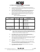
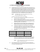
Table Of Contents
- T3CAS_Section_5
- 5 Adjustment/Test
- 1. General
- 2. Equipment
- 3. Initial Harness Checkout (New Installations Only)
- 4. System Self-Tests
- 5. Return-to-Service Test
- 6. Operational Software Loading Using an ARINC 615A Portable Data Loader or Compact Flash Card
- 7. Downloading Information from the TP3PCAS Using a CF Card
- 1. Obtain a New or Blank Compact Flash (CF) card.
- 2. Copy to the New or Blank CF card the appropriate ‘Header File’
- a) Header files are files copied to the New or Blank CF card that will instruct the computer unit what is desired to be downloaded.
- b) Header files needed to download Maintenance Data, Event Data and CRC Part Numbers can be obtained from ACSS Customer Services at +1-623-445-7070 or crc.acss@l-3com.com.
- 3. For downloading Maintenance Data, Event Data or CRC Part Numbers the aircraft does not need to be in an on-ground configuration.
- 4. Apply power to the computer unit.
- 5. Insert the CF card.
- 6. For ACSS part numbers 9005000-10000, -10101, -10202, and -10204 the DATA STATUS LED will UblinkU green once; this indicates the unit recognized that a CF card was inserted.
- 7. For ACSS part numbers 9005000-11203, -11801 and -55801 the DATA STATUS LED will UblinkU green while reading the header file and performing the action defined in the header file.
- 8. Flight Data Recording
- 1. T3CAS part numbers 9005000-10000, -10101, -10202, and -10204 only support FAT16 CF card formatting. T3CAS part numbers 9005000-11203, -11801 and -55801 support both FAT16 and FAT32 CF card formatting.
- B. Flight Data
- 1. Obtain a New or Blank CF Card.
- 2. Copy to the New or Blank CF Card the Appropriate Header File.
- 3. Header files are files copied to the New or Blank CF card that will instruct the computer unit what is desired to be downloaded.
- 4. For Flight Data Recording, the aircraft does not need to be in an on-ground configuration.
- 5. Apply power to the computer unit.
- 6. Insert the CF card.
- B. Flight Data
- 9. Downloaded Maintenance Data, Event Data And Flight Data May Be Sent To ACSS Customer Services For Analysis
- 5 Adjustment/Test
- T3CAS_Section_6
- T3CAS_Section_7
- 7 Maintenance Practices
- 1. General
- 2. Equipment and Materials
- 3. Procedure for the TP3PCAS Computer Unit
- 4. Procedure for the APM (Not applicable for part numbers 9005000-10000, -10101, -10202, -10204, or -11203)
- 5. Procedure for the Directional Antenna
- 6. Procedure for the Omnidirectional Antenna (Applicable to part numbers 9005000-11203, -11801 and -55801)
- 7. Procedure for the Control Panel
- 8. Procedure for the VSI/TRA Display
- 9. Instructions for Continued Airworthiness, FAR Part 25.1529
- 7 Maintenance Practices
- T3CAS_Section_8
- T3CAS_Section_9
- T3CAS_Section_10
- T3CAS_Appendix_A

SYSTEM DESCRIPTION AND INSTALLATION MANUAL
T
3
CAS/Part No.9005000
(5) If an open circuit, short circuit, or unacceptable resistance measurement is
detected on the directional antenna path, a failure has occurred in the connector,
coax cable, or directional antenna.
(6) Locate the directional antenna that has a suspected failure. Remove the coax
cable from the antenna port that is suspected to have failed. Isolate which
section of the antenna system is at fault by a process of elimination. The
resistance values of the antenna ports should be as specified in Table 6-12.
(7) Remove and replace the appropriate failed component in accordance with
approved AMM procedures.
Table 6-13: Antenna Wiring Resistance
Antenna
Connector
Section
Pin dc Resistance
Top Directional Antenna
LTP
1
2
3
4
1,000 ±100 ohms
8,060 ±800 ohms
4,020 ±400 ohms
2,000 ±200 ohms
Bottom Directional Antenna
LMP
1
2
3
4
1,000 ±100 ohms
8,060 ±800 ohms
4,020 ±400 ohms
2,000 ±200 ohms
Optional Bottom
Omnidirectional Antenna
for part numbers 9005000-
11203, -11801 and -55801.
LMP
1
2
3
4
0 to 50 ohms (50 ohms maximum)
Infinite (>50k ohms)
Infinite (>50k ohms)
Infinite (>50k ohms)
NOTE:
The procedures that follow are recommended for intermittent antenna system
failures or if the continuity tests have not identified a failed component in the
antenna system or if the flight crew detects an unacceptable visual discrepancy
between an intruder aircraft and its displayed location.
(8) If the displayed location of an intruder aircraft is believed to be in error,
appropriate ramp test equipment can be used to simulate intruder aircraft to
check the suspected discrepancy while on the ground.
(9) Remove the suspected TCAS directional antenna and terminate the antenna side
of the cable with a 50-ohm termination (Omni-Spectra Part Number 3102-6100-
00 or equivalent TNC jack with VSWR ≤1.15 : 1).
(10) Perform a thorough inspection for moisture or contamination of all coax cable
assemblies.
(11) Remove the T
3
CAS LRU and do a VSWR check on the coax cable from the
T
3
CAS computer tray side. Use approved VSWR test equipment and operating
procedures. The measured VSWR should be less than 2.0 : 1.
(12) If the VSWR test fails, isolate failed antenna coax section. Remove/repair
appropriate cable and/or connector.
Pub. No. 8600200-001, Revision 004
34-45-29
6-57
04 Nov2014
Use or disclosure of information on this page is subject to the restrictions in the proprietary notice of this document.