
User's Manual
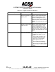
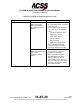
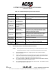
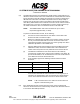
Table Of Contents
- T3CAS_Section_5
- 5 Adjustment/Test
- 1. General
- 2. Equipment
- 3. Initial Harness Checkout (New Installations Only)
- 4. System Self-Tests
- 5. Return-to-Service Test
- 6. Operational Software Loading Using an ARINC 615A Portable Data Loader or Compact Flash Card
- 7. Downloading Information from the TP3PCAS Using a CF Card
- 1. Obtain a New or Blank Compact Flash (CF) card.
- 2. Copy to the New or Blank CF card the appropriate ‘Header File’
- a) Header files are files copied to the New or Blank CF card that will instruct the computer unit what is desired to be downloaded.
- b) Header files needed to download Maintenance Data, Event Data and CRC Part Numbers can be obtained from ACSS Customer Services at +1-623-445-7070 or crc.acss@l-3com.com.
- 3. For downloading Maintenance Data, Event Data or CRC Part Numbers the aircraft does not need to be in an on-ground configuration.
- 4. Apply power to the computer unit.
- 5. Insert the CF card.
- 6. For ACSS part numbers 9005000-10000, -10101, -10202, and -10204 the DATA STATUS LED will UblinkU green once; this indicates the unit recognized that a CF card was inserted.
- 7. For ACSS part numbers 9005000-11203, -11801 and -55801 the DATA STATUS LED will UblinkU green while reading the header file and performing the action defined in the header file.
- 8. Flight Data Recording
- 1. T3CAS part numbers 9005000-10000, -10101, -10202, and -10204 only support FAT16 CF card formatting. T3CAS part numbers 9005000-11203, -11801 and -55801 support both FAT16 and FAT32 CF card formatting.
- B. Flight Data
- 1. Obtain a New or Blank CF Card.
- 2. Copy to the New or Blank CF Card the Appropriate Header File.
- 3. Header files are files copied to the New or Blank CF card that will instruct the computer unit what is desired to be downloaded.
- 4. For Flight Data Recording, the aircraft does not need to be in an on-ground configuration.
- 5. Apply power to the computer unit.
- 6. Insert the CF card.
- B. Flight Data
- 9. Downloaded Maintenance Data, Event Data And Flight Data May Be Sent To ACSS Customer Services For Analysis
- 5 Adjustment/Test
- T3CAS_Section_6
- T3CAS_Section_7
- 7 Maintenance Practices
- 1. General
- 2. Equipment and Materials
- 3. Procedure for the TP3PCAS Computer Unit
- 4. Procedure for the APM (Not applicable for part numbers 9005000-10000, -10101, -10202, -10204, or -11203)
- 5. Procedure for the Directional Antenna
- 6. Procedure for the Omnidirectional Antenna (Applicable to part numbers 9005000-11203, -11801 and -55801)
- 7. Procedure for the Control Panel
- 8. Procedure for the VSI/TRA Display
- 9. Instructions for Continued Airworthiness, FAR Part 25.1529
- 7 Maintenance Practices
- T3CAS_Section_8
- T3CAS_Section_9
- T3CAS_Section_10
- T3CAS_Appendix_A

SYSTEM DESCRIPTION AND INSTALLATION MANUAL
T
3
CAS/Part No.9005000
Table 6-12: T
3
CAS Fault Reporting and Corrective Actions
Status
Annunciator
Failure Possible Corrective Action
T
3
CAS P/F
Status is Green
The T
3
CAS function
passes its own internal
BITE test
T
3
CAS function is operational. If other annunciators
are on, the problem is in the indicated subsystem or
aircraft wiring.
T
3
CAS P/F
Status is Solid
Red
The T
3
CAS function
has failed its own
internal BITE test
Replace the T
3
CAS computer unit.
T
3
CAS P/F
Status is
Blinking Red
The T
3
CAS function
has failed its own
internal BITE test within
the Boot
Replace the T
3
CAS computer unit.
TOP ANT
The top antenna dc
resistance test
indicates a failure
Remove the T
3
CAS computer unit. Use a multimeter
to measure the dc resistances indicated in Table
6-12
for the top antenna. Repair antenna cables or
replace the antenna as required.
BOT ANT
The bottom antenna dc
resistance test
indicates a failure
Remove the T
3
CAS computer unit. Use a multimeter
to measure the dc resistance indicated in Table
6-12
for the bottom antenna. Repair antenna
cable(s) or replace the antenna as required.
Data Status is
Solid Amber
Loading Failure
Re-attempt the dataload.
Data Status is
Blinking Amber
Bad Media or
Configuration Failure
Verify the dataload media is not corrupted and that
the T
3
CAS is configured for dataloading.
External IO
Status
External IO Interface is
Failed
Check wiring and power to external IO devices.
F. Directional Antenna Test/Fault Isolation Procedure
NOTE:
These procedures are recommended only if a T
3
CAS TCAS function BITE or
extended test failure of the top or bottom directional antenna has occurred.
(1) Review extended maintenance or flight leg BITE data to determine which
antenna has failed.
(2) Remove T
3
CAS computer unit from mounting tray. Visually examine all antenna
coax cable connectors at the mounting tray side as well as the LRU connectors.
Remove any foreign material discovered and reinstall the LRU.
(3) Do a system self-test to determine if the fault has cleared. If the failure continues,
remove the T
3
CAS computer unit and proceed.
(4) Do a continuity test at the LRU end of each antenna cable. The resistance values
should be as specified in Table 6-12.
6-56
04 Nov 2014
34-45-29
Pub. No. 8600200-001, Revision 004
Use or disclosure of information on this page is subject to the restrictions in the proprietary notice of this document.