
User's Manual
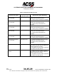
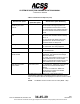
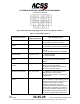
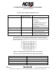
Table Of Contents
- T3CAS_Section_5
- 5 Adjustment/Test
- 1. General
- 2. Equipment
- 3. Initial Harness Checkout (New Installations Only)
- 4. System Self-Tests
- 5. Return-to-Service Test
- 6. Operational Software Loading Using an ARINC 615A Portable Data Loader or Compact Flash Card
- 7. Downloading Information from the TP3PCAS Using a CF Card
- 1. Obtain a New or Blank Compact Flash (CF) card.
- 2. Copy to the New or Blank CF card the appropriate ‘Header File’
- a) Header files are files copied to the New or Blank CF card that will instruct the computer unit what is desired to be downloaded.
- b) Header files needed to download Maintenance Data, Event Data and CRC Part Numbers can be obtained from ACSS Customer Services at +1-623-445-7070 or crc.acss@l-3com.com.
- 3. For downloading Maintenance Data, Event Data or CRC Part Numbers the aircraft does not need to be in an on-ground configuration.
- 4. Apply power to the computer unit.
- 5. Insert the CF card.
- 6. For ACSS part numbers 9005000-10000, -10101, -10202, and -10204 the DATA STATUS LED will UblinkU green once; this indicates the unit recognized that a CF card was inserted.
- 7. For ACSS part numbers 9005000-11203, -11801 and -55801 the DATA STATUS LED will UblinkU green while reading the header file and performing the action defined in the header file.
- 8. Flight Data Recording
- 1. T3CAS part numbers 9005000-10000, -10101, -10202, and -10204 only support FAT16 CF card formatting. T3CAS part numbers 9005000-11203, -11801 and -55801 support both FAT16 and FAT32 CF card formatting.
- B. Flight Data
- 1. Obtain a New or Blank CF Card.
- 2. Copy to the New or Blank CF Card the Appropriate Header File.
- 3. Header files are files copied to the New or Blank CF card that will instruct the computer unit what is desired to be downloaded.
- 4. For Flight Data Recording, the aircraft does not need to be in an on-ground configuration.
- 5. Apply power to the computer unit.
- 6. Insert the CF card.
- B. Flight Data
- 9. Downloaded Maintenance Data, Event Data And Flight Data May Be Sent To ACSS Customer Services For Analysis
- 5 Adjustment/Test
- T3CAS_Section_6
- T3CAS_Section_7
- 7 Maintenance Practices
- 1. General
- 2. Equipment and Materials
- 3. Procedure for the TP3PCAS Computer Unit
- 4. Procedure for the APM (Not applicable for part numbers 9005000-10000, -10101, -10202, -10204, or -11203)
- 5. Procedure for the Directional Antenna
- 6. Procedure for the Omnidirectional Antenna (Applicable to part numbers 9005000-11203, -11801 and -55801)
- 7. Procedure for the Control Panel
- 8. Procedure for the VSI/TRA Display
- 9. Instructions for Continued Airworthiness, FAR Part 25.1529
- 7 Maintenance Practices
- T3CAS_Section_8
- T3CAS_Section_9
- T3CAS_Section_10
- T3CAS_Appendix_A

SYSTEM DESCRIPTION AND INSTALLATION MANUAL
T
3
CAS/Part No.9005000
Figure 6-48: ACD Option Page (Page 24/25) – Display Alert Line Aperture
The Maintenance ACD Options Page 25/25 displays the ACD Runway Location Error
Options, as shown in Figure 6-49. This value plus 100 meters (328.084 feet) or 0.05
nautical miles represents the runway location error used for the landing tunnel half-width
computation in the CPA logic (unit Nm), when navigation accuracy is high (accurate).
When accuracy is lower (less accurate), the landing tunnel half-width increases beyond
this level.
Figure 6-49: ACD Option Page (Page 25/25) – Runway Location Error
E. T
3
CAS Computer Unit Self-Test
The T
3
CAS computer unit detects system faults and stores them in its internal memory.
Using the push-to-test button on the front panel of the LRU, these faults can be displayed
on its front panel annunciator for (up to) the last 10 flight legs. A flight leg is the interval
between weight-off-wheels and weight-on-wheels during which T
3
CAS is operative. By
recalling the stored data, ground maintenance personnel can evaluate in-flight
performance on the ground and fault-isolate a current or previous failure to a specific
LRU or LRU interface.
Table 6-10 summarizes how the T
3
CAS computer unit self-test is activated at power-up,
during operation, and during commanded self-test. The computer unit can activate the
commanded self-test only when the aircraft is on the ground.
Table 6-11 lists the functions of the computer unit’s status annunciators and the
corresponding troubleshooting actions. If the annunciators indicate an antenna problem,
the antenna connections should be checked by measuring the antenna resistance values
at the computer unit mounting tray. The resistance values listed in Table 6-12 are
measured between the center conductor and shield on each LTP and LMP antenna
connector.
Pub. No. 8600200-001, Revision 004
34-45-29
6-53
04 Nov2014
Use or disclosure of information on this page is subject to the restrictions in the proprietary notice of this document.