
User's Manual
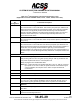
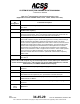
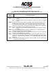
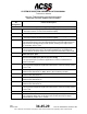
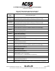
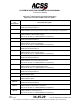
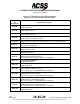
Table Of Contents
- T3CAS_Section_5
- 5 Adjustment/Test
- 1. General
- 2. Equipment
- 3. Initial Harness Checkout (New Installations Only)
- 4. System Self-Tests
- 5. Return-to-Service Test
- 6. Operational Software Loading Using an ARINC 615A Portable Data Loader or Compact Flash Card
- 7. Downloading Information from the TP3PCAS Using a CF Card
- 1. Obtain a New or Blank Compact Flash (CF) card.
- 2. Copy to the New or Blank CF card the appropriate ‘Header File’
- a) Header files are files copied to the New or Blank CF card that will instruct the computer unit what is desired to be downloaded.
- b) Header files needed to download Maintenance Data, Event Data and CRC Part Numbers can be obtained from ACSS Customer Services at +1-623-445-7070 or crc.acss@l-3com.com.
- 3. For downloading Maintenance Data, Event Data or CRC Part Numbers the aircraft does not need to be in an on-ground configuration.
- 4. Apply power to the computer unit.
- 5. Insert the CF card.
- 6. For ACSS part numbers 9005000-10000, -10101, -10202, and -10204 the DATA STATUS LED will UblinkU green once; this indicates the unit recognized that a CF card was inserted.
- 7. For ACSS part numbers 9005000-11203, -11801 and -55801 the DATA STATUS LED will UblinkU green while reading the header file and performing the action defined in the header file.
- 8. Flight Data Recording
- 1. T3CAS part numbers 9005000-10000, -10101, -10202, and -10204 only support FAT16 CF card formatting. T3CAS part numbers 9005000-11203, -11801 and -55801 support both FAT16 and FAT32 CF card formatting.
- B. Flight Data
- 1. Obtain a New or Blank CF Card.
- 2. Copy to the New or Blank CF Card the Appropriate Header File.
- 3. Header files are files copied to the New or Blank CF card that will instruct the computer unit what is desired to be downloaded.
- 4. For Flight Data Recording, the aircraft does not need to be in an on-ground configuration.
- 5. Apply power to the computer unit.
- 6. Insert the CF card.
- B. Flight Data
- 9. Downloaded Maintenance Data, Event Data And Flight Data May Be Sent To ACSS Customer Services For Analysis
- 5 Adjustment/Test
- T3CAS_Section_6
- T3CAS_Section_7
- 7 Maintenance Practices
- 1. General
- 2. Equipment and Materials
- 3. Procedure for the TP3PCAS Computer Unit
- 4. Procedure for the APM (Not applicable for part numbers 9005000-10000, -10101, -10202, -10204, or -11203)
- 5. Procedure for the Directional Antenna
- 6. Procedure for the Omnidirectional Antenna (Applicable to part numbers 9005000-11203, -11801 and -55801)
- 7. Procedure for the Control Panel
- 8. Procedure for the VSI/TRA Display
- 9. Instructions for Continued Airworthiness, FAR Part 25.1529
- 7 Maintenance Practices
- T3CAS_Section_8
- T3CAS_Section_9
- T3CAS_Section_10
- T3CAS_Appendix_A

SYSTEM DESCRIPTION AND INSTALLATION MANUAL
T
3
CAS/Part No.9005000
Table 4-1: T
3
CAS Computer Unit Interface Description (cont)
(Applicable to Part No. 9005000-10000, -10101, -10202, -10204, and -11203)
Connector
Pin
Designation
Functional Description
J1-16
Input Bus Shields
The shields from the input bus (J1-1, 2) should be connected to this pin.
J1-17
Spare Pin
J1-18
PDL Link A Discrete Input
Reserved.
J1-19
PDL Link B Common
Reserved..
J1-20, 22
115 V ac Power Output: [J1-20 (H), J1-22 (C)]
These power output pins provide the 115 V ac operating power for the data loader.
The 115 V ac (H) and 115 V ac (C) interconnect wires should be shielded or
twisted and shielded with an insulating jacket over the shield. The shield should be
connected to chassis ground (J1-21).
J1-21
Chassis Ground
Connect 115 V ac power shields to this pin.
J1-23
A615A Dataloader Ethernet Input (RD+)
TAWS Ethernet 10-base-T read input
J1-24,
Thru
J1-27
Spare Pins
J1-28
Output Bus Shields
J1-29
Thru
J1-32
Spare Pins
J1-33,34
ARINC 429 TA/RA Display No.1 Output: [J1-33 (A), J1-34 (B)]
This bus can be used to connect to a maintenance display. These pins are also
connected to the ARINC 600 connector on the rear of the unit (RMP-7C and -7D).
J1-35,
J1-36
Spare Pins
J1-37, 38
28 V dc Power Output: [J1-37 (HI), J1-38 (LO)]
These pins supply +28 V dc, 30 W nominal power for a portable data loader (PDL).
These pins are used only if the PDL operates from +28 V dc.
J1-39
A615A Dataloader Ethernet Input (RD-)
TAWS Ethernet 10-base-T read input
J1-40
RS-232 Data Input #1
This input is used by the T
3
CAS to receive RS- 232 data from a portable
maintenance terminal.
Pub. No. 8600200-001, Revision 004
34-45-29
4-35
04 Nov 2014
Use or disclosure of information on this page is subject to the restrictions in the proprietary notice of this document.