
User's Manual
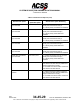
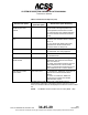
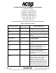
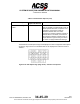
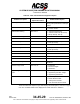
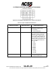
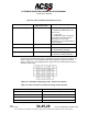
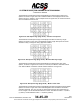
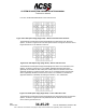
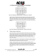
Table Of Contents
- T3CAS_Section_5
- 5 Adjustment/Test
- 1. General
- 2. Equipment
- 3. Initial Harness Checkout (New Installations Only)
- 4. System Self-Tests
- 5. Return-to-Service Test
- 6. Operational Software Loading Using an ARINC 615A Portable Data Loader or Compact Flash Card
- 7. Downloading Information from the TP3PCAS Using a CF Card
- 1. Obtain a New or Blank Compact Flash (CF) card.
- 2. Copy to the New or Blank CF card the appropriate ‘Header File’
- a) Header files are files copied to the New or Blank CF card that will instruct the computer unit what is desired to be downloaded.
- b) Header files needed to download Maintenance Data, Event Data and CRC Part Numbers can be obtained from ACSS Customer Services at +1-623-445-7070 or crc.acss@l-3com.com.
- 3. For downloading Maintenance Data, Event Data or CRC Part Numbers the aircraft does not need to be in an on-ground configuration.
- 4. Apply power to the computer unit.
- 5. Insert the CF card.
- 6. For ACSS part numbers 9005000-10000, -10101, -10202, and -10204 the DATA STATUS LED will UblinkU green once; this indicates the unit recognized that a CF card was inserted.
- 7. For ACSS part numbers 9005000-11203, -11801 and -55801 the DATA STATUS LED will UblinkU green while reading the header file and performing the action defined in the header file.
- 8. Flight Data Recording
- 1. T3CAS part numbers 9005000-10000, -10101, -10202, and -10204 only support FAT16 CF card formatting. T3CAS part numbers 9005000-11203, -11801 and -55801 support both FAT16 and FAT32 CF card formatting.
- B. Flight Data
- 1. Obtain a New or Blank CF Card.
- 2. Copy to the New or Blank CF Card the Appropriate Header File.
- 3. Header files are files copied to the New or Blank CF card that will instruct the computer unit what is desired to be downloaded.
- 4. For Flight Data Recording, the aircraft does not need to be in an on-ground configuration.
- 5. Apply power to the computer unit.
- 6. Insert the CF card.
- B. Flight Data
- 9. Downloaded Maintenance Data, Event Data And Flight Data May Be Sent To ACSS Customer Services For Analysis
- 5 Adjustment/Test
- T3CAS_Section_6
- T3CAS_Section_7
- 7 Maintenance Practices
- 1. General
- 2. Equipment and Materials
- 3. Procedure for the TP3PCAS Computer Unit
- 4. Procedure for the APM (Not applicable for part numbers 9005000-10000, -10101, -10202, -10204, or -11203)
- 5. Procedure for the Directional Antenna
- 6. Procedure for the Omnidirectional Antenna (Applicable to part numbers 9005000-11203, -11801 and -55801)
- 7. Procedure for the Control Panel
- 8. Procedure for the VSI/TRA Display
- 9. Instructions for Continued Airworthiness, FAR Part 25.1529
- 7 Maintenance Practices
- T3CAS_Section_8
- T3CAS_Section_9
- T3CAS_Section_10
- T3CAS_Appendix_A

SYSTEM DESCRIPTION AND INSTALLATION MANUAL
T
3
CAS/Part No.9005000
The Maintenance ACD Options Page 18/25 displays the ACD Mode 6 Volume Level
Options as shown in Figure 6-42. The correlations table for the displayed volume level
values is shown in Table 6-9. In the example shown in Figure 6-42, the volume levels are
set to a middle level value of 128.
Figure 6-42: ACD Option Page (Page 18/25) – Volume Level Options
The Maintenance ACD Options Page 19/25 displays the Minimum Runway Length
Options as shown in Figure 6-43. The Minimum Runway Length ACD option is used to
calculate runway convergence during approach inhibition.
Figure 6-43: ACD Option Page (Page 19/25) – Minimum Runway Length
The Maintenance ACD Options Page 20/25 displays the ACD Mode 2 Latch Time
Options, as shown in Figure 6-44. The time, in seconds, that Mode 2 will remain armed
even after the Mode 2 Activation Vertical Offset threshold is no longer met.
Figure 6-44: ACD Option Page (Page 20/25) - Mode 2 Latch Time
The Maintenance ACD Options Page 21/25 displays the Mode 2 Activation Vertical Offset
Options as shown in Figure 6-45. The Positive/Negative offset is added to the Mode 2
activation threshold. This is to account for cases where a terrain cell is coded with too
low of a height or an aircraft lateral/vertical error exists. The Minimum Value = -10,000 ft
(-3,048 m). and the Maximum Value = +10,000 ft (3,048 m).
Pub. No. 8600200-001, Revision 004
34-45-29
6-51
04 Nov2014
Use or disclosure of information on this page is subject to the restrictions in the proprietary notice of this document.