
User's Manual
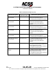
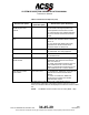
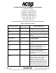
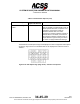
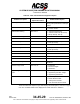
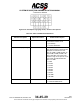
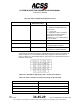
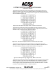
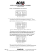
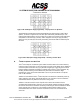
Table Of Contents
- T3CAS_Section_5
- 5 Adjustment/Test
- 1. General
- 2. Equipment
- 3. Initial Harness Checkout (New Installations Only)
- 4. System Self-Tests
- 5. Return-to-Service Test
- 6. Operational Software Loading Using an ARINC 615A Portable Data Loader or Compact Flash Card
- 7. Downloading Information from the TP3PCAS Using a CF Card
- 1. Obtain a New or Blank Compact Flash (CF) card.
- 2. Copy to the New or Blank CF card the appropriate ‘Header File’
- a) Header files are files copied to the New or Blank CF card that will instruct the computer unit what is desired to be downloaded.
- b) Header files needed to download Maintenance Data, Event Data and CRC Part Numbers can be obtained from ACSS Customer Services at +1-623-445-7070 or crc.acss@l-3com.com.
- 3. For downloading Maintenance Data, Event Data or CRC Part Numbers the aircraft does not need to be in an on-ground configuration.
- 4. Apply power to the computer unit.
- 5. Insert the CF card.
- 6. For ACSS part numbers 9005000-10000, -10101, -10202, and -10204 the DATA STATUS LED will UblinkU green once; this indicates the unit recognized that a CF card was inserted.
- 7. For ACSS part numbers 9005000-11203, -11801 and -55801 the DATA STATUS LED will UblinkU green while reading the header file and performing the action defined in the header file.
- 8. Flight Data Recording
- 1. T3CAS part numbers 9005000-10000, -10101, -10202, and -10204 only support FAT16 CF card formatting. T3CAS part numbers 9005000-11203, -11801 and -55801 support both FAT16 and FAT32 CF card formatting.
- B. Flight Data
- 1. Obtain a New or Blank CF Card.
- 2. Copy to the New or Blank CF Card the Appropriate Header File.
- 3. Header files are files copied to the New or Blank CF card that will instruct the computer unit what is desired to be downloaded.
- 4. For Flight Data Recording, the aircraft does not need to be in an on-ground configuration.
- 5. Apply power to the computer unit.
- 6. Insert the CF card.
- B. Flight Data
- 9. Downloaded Maintenance Data, Event Data And Flight Data May Be Sent To ACSS Customer Services For Analysis
- 5 Adjustment/Test
- T3CAS_Section_6
- T3CAS_Section_7
- 7 Maintenance Practices
- 1. General
- 2. Equipment and Materials
- 3. Procedure for the TP3PCAS Computer Unit
- 4. Procedure for the APM (Not applicable for part numbers 9005000-10000, -10101, -10202, -10204, or -11203)
- 5. Procedure for the Directional Antenna
- 6. Procedure for the Omnidirectional Antenna (Applicable to part numbers 9005000-11203, -11801 and -55801)
- 7. Procedure for the Control Panel
- 8. Procedure for the VSI/TRA Display
- 9. Instructions for Continued Airworthiness, FAR Part 25.1529
- 7 Maintenance Practices
- T3CAS_Section_8
- T3CAS_Section_9
- T3CAS_Section_10
- T3CAS_Appendix_A

SYSTEM DESCRIPTION AND INSTALLATION MANUAL
T
3
CAS/Part No.9005000
Table 6-5: ACD Discrete Options (cont)
ACD Discrete Option
ACD Discrete
Option Bit Option
ACD Discrete Option Bit Setting
Mode 6 Volume Level
Disable System Test
Callouts
Hex Char 7, bit 2
1 = Cause System Test Callouts to be
annunciated at the High-Impedance or
Low-Impedance Normal Volume Levels.
0 = Cause System Test Callouts indicated
to be annunciated at the Mode 6 Volume
Level.
Positive FPA Limit for slice
calc
Hex Char 7, bit 1
1 = Any Sharp FPA greater than 0 results
in terrain slice coloration based on Sharp
FPA = 0.
0 = Any Sharp FPA (Flight Path Angle)
greater than 0 results in terrain slice
coloration based on Sharp FPA.
TAL Approach Activation
Hex Char 8, bit 4
1 = Activate TAL during approach.
0 = Deactivate TAL during approach
Mode 1 Disable
Hex Char 8, bit 3
1 = Disable Mode 1
0 = Enable Mode 1
TAL Lookahead 30 S
MAAS Disable
Hex Char 8, bit 2
1 = TAL is always calculated using 120-sec
lookahead. This represents the heritage
Alert Line distance.
0 = When in Mountainous Airport Area, the
TAL lookahead is set to 30 sec ahead.
When not in Mountainous Airport Area, the
TAL lookahead is set to 120 sec ahead.
Basic Runway Inhibit
Annunciation
Hex Char 8, bit 1
1 = Enables the ”TERR N/A” annunciator to
activate when GCAM indicates Basic
Airport.
0 = Does not enable the ”TERR N/A”
annunciator to activate when GCAM
indicates Basic Airport.
The Maintenance ACD Options Page 14/25 displays the hex
representation of Boolean Configuration Options as shown in Figure
6-38. The correlation table for the displayed hex values is shown in Table
6-6.
NOTE:
The MSB is the left most bit in the Hex value (MSB .. LSB).
Pub. No. 8600200-001, Revision 004
34-45-29
6-45
04 Nov2014
Use or disclosure of information on this page is subject to the restrictions in the proprietary notice of this document.