
User's Manual
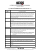
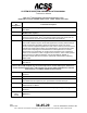
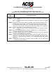
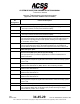
Table Of Contents
- T3CAS_Section_5
- 5 Adjustment/Test
- 1. General
- 2. Equipment
- 3. Initial Harness Checkout (New Installations Only)
- 4. System Self-Tests
- 5. Return-to-Service Test
- 6. Operational Software Loading Using an ARINC 615A Portable Data Loader or Compact Flash Card
- 7. Downloading Information from the TP3PCAS Using a CF Card
- 1. Obtain a New or Blank Compact Flash (CF) card.
- 2. Copy to the New or Blank CF card the appropriate ‘Header File’
- a) Header files are files copied to the New or Blank CF card that will instruct the computer unit what is desired to be downloaded.
- b) Header files needed to download Maintenance Data, Event Data and CRC Part Numbers can be obtained from ACSS Customer Services at +1-623-445-7070 or crc.acss@l-3com.com.
- 3. For downloading Maintenance Data, Event Data or CRC Part Numbers the aircraft does not need to be in an on-ground configuration.
- 4. Apply power to the computer unit.
- 5. Insert the CF card.
- 6. For ACSS part numbers 9005000-10000, -10101, -10202, and -10204 the DATA STATUS LED will UblinkU green once; this indicates the unit recognized that a CF card was inserted.
- 7. For ACSS part numbers 9005000-11203, -11801 and -55801 the DATA STATUS LED will UblinkU green while reading the header file and performing the action defined in the header file.
- 8. Flight Data Recording
- 1. T3CAS part numbers 9005000-10000, -10101, -10202, and -10204 only support FAT16 CF card formatting. T3CAS part numbers 9005000-11203, -11801 and -55801 support both FAT16 and FAT32 CF card formatting.
- B. Flight Data
- 1. Obtain a New or Blank CF Card.
- 2. Copy to the New or Blank CF Card the Appropriate Header File.
- 3. Header files are files copied to the New or Blank CF card that will instruct the computer unit what is desired to be downloaded.
- 4. For Flight Data Recording, the aircraft does not need to be in an on-ground configuration.
- 5. Apply power to the computer unit.
- 6. Insert the CF card.
- B. Flight Data
- 9. Downloaded Maintenance Data, Event Data And Flight Data May Be Sent To ACSS Customer Services For Analysis
- 5 Adjustment/Test
- T3CAS_Section_6
- T3CAS_Section_7
- 7 Maintenance Practices
- 1. General
- 2. Equipment and Materials
- 3. Procedure for the TP3PCAS Computer Unit
- 4. Procedure for the APM (Not applicable for part numbers 9005000-10000, -10101, -10202, -10204, or -11203)
- 5. Procedure for the Directional Antenna
- 6. Procedure for the Omnidirectional Antenna (Applicable to part numbers 9005000-11203, -11801 and -55801)
- 7. Procedure for the Control Panel
- 8. Procedure for the VSI/TRA Display
- 9. Instructions for Continued Airworthiness, FAR Part 25.1529
- 7 Maintenance Practices
- T3CAS_Section_8
- T3CAS_Section_9
- T3CAS_Section_10
- T3CAS_Appendix_A

SYSTEM DESCRIPTION AND INSTALLATION MANUAL
T
3
CAS/Part No.9005000
Table 4-1: T
3
CAS Computer Unit Interface Description (cont)
(Applicable to Part No. 9005000-10000, -10101, -10202, -10204, and -11203)
Connector
Pin
Designation
Functional Description
LBP-9
Fan 115 V ac Power Output (C)
See LBP-5.
LBP-10
28 VDC Power Input (+)
LBP-11
Chassis Ground
Connect to aircraft frame. The T
3
CAS Chassis and signal ground pins should use
the same AWG as the power connections (See LBP-1 and LBP-10).
LBP-12
Mutual Suppression Pulse Bus Input A
The T
3
CAS computer unit joins the mutual suppression bus daisy chained through
TCAS and other RF-transmitting equipment onboard the aircraft. The TCAS
function receives suppression pulses from other LRUs on this bus, which is used to
suppress the TCAS receivers during such transmissions. This prevents the TCAS
function from interpreting these transmissions as valid replies from an intruder
aircraft. When not suppressed, the TCAS function transmits its own suppression
pulses on the same bus in order to suppress the receivers in other L-band systems
on the aircraft. The L-Band suppression coax must be RG142, RG400, or
equivalent coaxial cable which meets the operational characteristics required by
ARINC 735A.
LBP-13
Mutual Suppression Pulse Bus Input B
See LBP-12.
The Interface descriptions that follow are for the 53-pin connector J1 mounted on the front
panel of the T
3
CAS computer unit. These descriptions are used to make up the cable that is
used to interface between the T
3
CAS computer unit and an ARINC 615A Ethernet, a RS-232
PC Serial Port, or an ARINC 429 Maintenance Display.
J1-1, 2
ARINC 429 PDL Bus Input: [J1-1 (A), J1-2 (B)]
Reserved.
J1-3, 4
Spare Pins
J1-5
Output Bus Shields
The shields from the output bus (J1-8, 9) should be connected to this pin.
J1-6, 7
A615A Data Loader Ethernet Output [J1-6 (TD+), J1-7 (TD-)]
TAWS Ethernet 10 Base-T.
J1-8, 9
ARINC 429 Data Loader/PDL Recorder Bus Output: [J1-8 (A), J1-9 (B)]
Reserved.
J1-10
Thru
J1-15
Spare Pins
4-34
04 Nov 2014
34-45-29
Pub. No. 8600200-001, Revision 004
Use or disclosure of information on this page is subject to the restrictions in the proprietary notice of this document.