
User's Manual
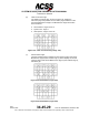
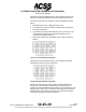
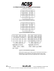
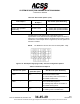
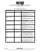
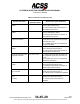
Table Of Contents
- T3CAS_Section_5
- 5 Adjustment/Test
- 1. General
- 2. Equipment
- 3. Initial Harness Checkout (New Installations Only)
- 4. System Self-Tests
- 5. Return-to-Service Test
- 6. Operational Software Loading Using an ARINC 615A Portable Data Loader or Compact Flash Card
- 7. Downloading Information from the TP3PCAS Using a CF Card
- 1. Obtain a New or Blank Compact Flash (CF) card.
- 2. Copy to the New or Blank CF card the appropriate ‘Header File’
- a) Header files are files copied to the New or Blank CF card that will instruct the computer unit what is desired to be downloaded.
- b) Header files needed to download Maintenance Data, Event Data and CRC Part Numbers can be obtained from ACSS Customer Services at +1-623-445-7070 or crc.acss@l-3com.com.
- 3. For downloading Maintenance Data, Event Data or CRC Part Numbers the aircraft does not need to be in an on-ground configuration.
- 4. Apply power to the computer unit.
- 5. Insert the CF card.
- 6. For ACSS part numbers 9005000-10000, -10101, -10202, and -10204 the DATA STATUS LED will UblinkU green once; this indicates the unit recognized that a CF card was inserted.
- 7. For ACSS part numbers 9005000-11203, -11801 and -55801 the DATA STATUS LED will UblinkU green while reading the header file and performing the action defined in the header file.
- 8. Flight Data Recording
- 1. T3CAS part numbers 9005000-10000, -10101, -10202, and -10204 only support FAT16 CF card formatting. T3CAS part numbers 9005000-11203, -11801 and -55801 support both FAT16 and FAT32 CF card formatting.
- B. Flight Data
- 1. Obtain a New or Blank CF Card.
- 2. Copy to the New or Blank CF Card the Appropriate Header File.
- 3. Header files are files copied to the New or Blank CF card that will instruct the computer unit what is desired to be downloaded.
- 4. For Flight Data Recording, the aircraft does not need to be in an on-ground configuration.
- 5. Apply power to the computer unit.
- 6. Insert the CF card.
- B. Flight Data
- 9. Downloaded Maintenance Data, Event Data And Flight Data May Be Sent To ACSS Customer Services For Analysis
- 5 Adjustment/Test
- T3CAS_Section_6
- T3CAS_Section_7
- 7 Maintenance Practices
- 1. General
- 2. Equipment and Materials
- 3. Procedure for the TP3PCAS Computer Unit
- 4. Procedure for the APM (Not applicable for part numbers 9005000-10000, -10101, -10202, -10204, or -11203)
- 5. Procedure for the Directional Antenna
- 6. Procedure for the Omnidirectional Antenna (Applicable to part numbers 9005000-11203, -11801 and -55801)
- 7. Procedure for the Control Panel
- 8. Procedure for the VSI/TRA Display
- 9. Instructions for Continued Airworthiness, FAR Part 25.1529
- 7 Maintenance Practices
- T3CAS_Section_8
- T3CAS_Section_9
- T3CAS_Section_10
- T3CAS_Appendix_A

SYSTEM DESCRIPTION AND INSTALLATION MANUAL
T
3
CAS/Part No.9005000
Table 6-5: ACD Callout Options (cont)
Callout Option
ACD Callout Option
Bit Option
ACD Callout Option Bit Setting
Unknown Decision Height
Hex Char 7 (MSB), bit
3
2,500 ft (762 m) Callout
Enable Flag
Hex char 7, bit 2
1 = 2,500 ft (762 m) Callout Enabled
0 = 2,500 ft (762 m) Callout Disabled
Spare bit
The Maintenance ACD Options Page 13/25 displays the hex
representation of the ACD Discrete Configuration Options as shown in
Figure 6-37. The correlation table for the displayed hex values is shown
in Table 6-5. In the example shown in Figure 6-37, all of the options are
selected to enabled.
NOTE:
The MSB is the left most bit in the Hex value (MSB .. LSB).
Figure 6-37: ACD Option Page (Page 13/25) – Discrete Configuration Options
Table 6-6: ACD Discrete Options
ACD Discrete Option
ACD Discrete
Option Bit Option
ACD Discrete Option Bit Setting
GPWS Caution Flash
Enable
Hex Char 1 (MSB),
bit 4
1 = Caution lamp flashing for the duration
of the GPWS Caution Event,
0 = Caution lamp solid for the duration of
the GPWS Caution Event
GPWS Warning Flash
Enable
Hex Char 1 (MSB),
bit 3
1 = Warning lamp flashing for the duration
of the GPWS Warning Event,
0 = Warning lamp solid for the duration of
the GPWS Warning Event
Male Voice Enable
Hex Char 1 (MSB),
bit 2
1 = Enables the male alerting voice,
0 = Alerting voice is a female voice
Pub. No. 8600200-001, Revision 004
34-45-29
6-41
04 Nov2014
Use or disclosure of information on this page is subject to the restrictions in the proprietary notice of this document.