
User's Manual
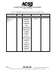
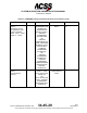
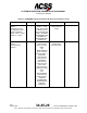
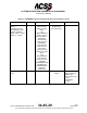
Table Of Contents
- T3CAS_Section_5
- 5 Adjustment/Test
- 1. General
- 2. Equipment
- 3. Initial Harness Checkout (New Installations Only)
- 4. System Self-Tests
- 5. Return-to-Service Test
- 6. Operational Software Loading Using an ARINC 615A Portable Data Loader or Compact Flash Card
- 7. Downloading Information from the TP3PCAS Using a CF Card
- 1. Obtain a New or Blank Compact Flash (CF) card.
- 2. Copy to the New or Blank CF card the appropriate ‘Header File’
- a) Header files are files copied to the New or Blank CF card that will instruct the computer unit what is desired to be downloaded.
- b) Header files needed to download Maintenance Data, Event Data and CRC Part Numbers can be obtained from ACSS Customer Services at +1-623-445-7070 or crc.acss@l-3com.com.
- 3. For downloading Maintenance Data, Event Data or CRC Part Numbers the aircraft does not need to be in an on-ground configuration.
- 4. Apply power to the computer unit.
- 5. Insert the CF card.
- 6. For ACSS part numbers 9005000-10000, -10101, -10202, and -10204 the DATA STATUS LED will UblinkU green once; this indicates the unit recognized that a CF card was inserted.
- 7. For ACSS part numbers 9005000-11203, -11801 and -55801 the DATA STATUS LED will UblinkU green while reading the header file and performing the action defined in the header file.
- 8. Flight Data Recording
- 1. T3CAS part numbers 9005000-10000, -10101, -10202, and -10204 only support FAT16 CF card formatting. T3CAS part numbers 9005000-11203, -11801 and -55801 support both FAT16 and FAT32 CF card formatting.
- B. Flight Data
- 1. Obtain a New or Blank CF Card.
- 2. Copy to the New or Blank CF Card the Appropriate Header File.
- 3. Header files are files copied to the New or Blank CF card that will instruct the computer unit what is desired to be downloaded.
- 4. For Flight Data Recording, the aircraft does not need to be in an on-ground configuration.
- 5. Apply power to the computer unit.
- 6. Insert the CF card.
- B. Flight Data
- 9. Downloaded Maintenance Data, Event Data And Flight Data May Be Sent To ACSS Customer Services For Analysis
- 5 Adjustment/Test
- T3CAS_Section_6
- T3CAS_Section_7
- 7 Maintenance Practices
- 1. General
- 2. Equipment and Materials
- 3. Procedure for the TP3PCAS Computer Unit
- 4. Procedure for the APM (Not applicable for part numbers 9005000-10000, -10101, -10202, -10204, or -11203)
- 5. Procedure for the Directional Antenna
- 6. Procedure for the Omnidirectional Antenna (Applicable to part numbers 9005000-11203, -11801 and -55801)
- 7. Procedure for the Control Panel
- 8. Procedure for the VSI/TRA Display
- 9. Instructions for Continued Airworthiness, FAR Part 25.1529
- 7 Maintenance Practices
- T3CAS_Section_8
- T3CAS_Section_9
- T3CAS_Section_10
- T3CAS_Appendix_A

SYSTEM DESCRIPTION AND INSTALLATION MANUAL
T
3
CAS/Part No.9005000
NOTES:
1.
If the transponder detects either all 1’s or all 0’s, the following message
will appear -ILLEGAL ADDRESS-. In addition, a fail message will appear
on the front of the transponder and on Extended Test. The message reads
CHECK DISCRETE ADDR WIRING ON XPDR PINS MP1A THROUGH
MP3D.
2.
The S/W PN information, line 8 of the display screen, displays general text
supplied by the ACSS ATDL transponder via label 356 (block transfer),
which is equipped to supply the text to the display. If a transponder is
installed that does not have this feature, line 8 is blank.
(f) Programming Pins Status Pages
The following three displays indicate the status of various option
programming pins located in the rear connector of the T
3
CAS computer.
The 1’s and 0’s following a programming option indicate the GROUND or
OPEN status for those programming pins. Each 1 and 0 is associated
with a program pin. A one (1) indicates the pin is grounded by connecting
to a program common pin on the T
3
CAS connector or to an aircraft
ground. A zero (0) indicates the pin is left open.
Selection of code 0004 displays the first of three pages that define
program pin status. See Figure 6-6.
Figure 6-6: Typical Program Pins 1/4 Page
Where more than one program pin is indicated, the listed connector pins
correspond to the display digits read from left to right. A one (1) indicates
the associated pin is grounded. A zero (0) indicates open.
Pub. No. 8600200-001, Revision 004
34-45-29
6-23
04 Nov2014
Use or disclosure of information on this page is subject to the restrictions in the proprietary notice of this document.