
User's Manual
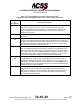
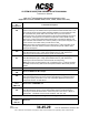
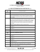
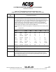
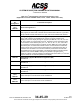
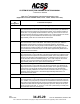
Table Of Contents
- T3CAS_Section_5
- 5 Adjustment/Test
- 1. General
- 2. Equipment
- 3. Initial Harness Checkout (New Installations Only)
- 4. System Self-Tests
- 5. Return-to-Service Test
- 6. Operational Software Loading Using an ARINC 615A Portable Data Loader or Compact Flash Card
- 7. Downloading Information from the TP3PCAS Using a CF Card
- 1. Obtain a New or Blank Compact Flash (CF) card.
- 2. Copy to the New or Blank CF card the appropriate ‘Header File’
- a) Header files are files copied to the New or Blank CF card that will instruct the computer unit what is desired to be downloaded.
- b) Header files needed to download Maintenance Data, Event Data and CRC Part Numbers can be obtained from ACSS Customer Services at +1-623-445-7070 or crc.acss@l-3com.com.
- 3. For downloading Maintenance Data, Event Data or CRC Part Numbers the aircraft does not need to be in an on-ground configuration.
- 4. Apply power to the computer unit.
- 5. Insert the CF card.
- 6. For ACSS part numbers 9005000-10000, -10101, -10202, and -10204 the DATA STATUS LED will UblinkU green once; this indicates the unit recognized that a CF card was inserted.
- 7. For ACSS part numbers 9005000-11203, -11801 and -55801 the DATA STATUS LED will UblinkU green while reading the header file and performing the action defined in the header file.
- 8. Flight Data Recording
- 1. T3CAS part numbers 9005000-10000, -10101, -10202, and -10204 only support FAT16 CF card formatting. T3CAS part numbers 9005000-11203, -11801 and -55801 support both FAT16 and FAT32 CF card formatting.
- B. Flight Data
- 1. Obtain a New or Blank CF Card.
- 2. Copy to the New or Blank CF Card the Appropriate Header File.
- 3. Header files are files copied to the New or Blank CF card that will instruct the computer unit what is desired to be downloaded.
- 4. For Flight Data Recording, the aircraft does not need to be in an on-ground configuration.
- 5. Apply power to the computer unit.
- 6. Insert the CF card.
- B. Flight Data
- 9. Downloaded Maintenance Data, Event Data And Flight Data May Be Sent To ACSS Customer Services For Analysis
- 5 Adjustment/Test
- T3CAS_Section_6
- T3CAS_Section_7
- 7 Maintenance Practices
- 1. General
- 2. Equipment and Materials
- 3. Procedure for the TP3PCAS Computer Unit
- 4. Procedure for the APM (Not applicable for part numbers 9005000-10000, -10101, -10202, -10204, or -11203)
- 5. Procedure for the Directional Antenna
- 6. Procedure for the Omnidirectional Antenna (Applicable to part numbers 9005000-11203, -11801 and -55801)
- 7. Procedure for the Control Panel
- 8. Procedure for the VSI/TRA Display
- 9. Instructions for Continued Airworthiness, FAR Part 25.1529
- 7 Maintenance Practices
- T3CAS_Section_8
- T3CAS_Section_9
- T3CAS_Section_10
- T3CAS_Appendix_A

SYSTEM DESCRIPTION AND INSTALLATION MANUAL
T
3
CAS/Part No.9005000
Table 4-1: T
3
CAS Computer Unit Interface Description (cont)
(Applicable to Part No. 9005000-10000, -10101, -10202, -10204, and -11203)
Connector
Pin
Designation
Functional Description
T
3
CAS Computer Unit Left Top Plug (LTP)
LTP-1
Top Antenna 0-Degree Port
J1 on the antenna is color-coded yellow. This antenna port (Note 2) is called the 0-
degree port because it produces a transmission pattern in the forward quadrant of
the aircraft. J1 is physically located toward the rear of the antenna and to the rear
of the aircraft when antenna is properly installed. The T
3
CAS computer unit checks
the built-in dc-to-ground resistance of this antenna port. It must detect
approximately 1000 ohms or TCAS fails its antenna test.
LTP-2
Top Antenna 270-Degree Port
J2 on the antenna is color-coded black. This antenna port (Note 2) is called the
270-degree port because it produces a transmission pattern in the left-wing
quadrant of the aircraft. J2 is physically located toward the right wing of the aircraft
when antenna is properly installed. The TCAS function checks the built-in dc-to-
ground resistance of this antenna port. It must detect approximately 8000 ohms or
it reports antenna test failure.
LTP-3
Top Antenna 180-Degree Port
J3 on the antenna is color-coded blue. This antenna port (Note 2) is called the 180-
degree port because it produces a transmission pattern in the rear quadrant of the
aircraft. J3 is physically located toward the front of the antenna and to the front of
the aircraft when antenna is installed properly. The T
3
CAS computer unit checks
the built-in dc-to-ground resistance of this antenna port. It must detect
approximately 4000 ohms or it reports antenna test failure.
LTP-4
Top Antenna 90-Degree Port
J4 on the antenna is color-coded red. This antenna port (Note 2) is called the 90-
degree port because it produces a transmission pattern in the right-wing quadrant
of the aircraft. J4 is physically located toward the left wing of the aircraft when
antenna is properly installed. The TCAS function checks the built-in dc-to-ground
resistance of this antenna port. It must detect approximately 2000 ohms or it
reports antenna test failure.
T
3
CAS Computer Unit Left Middle Plug (LMP)
LMP-1
Bottom Antenna 0-Degree Port
J1 on the antenna is color-coded yellow. Same as top antenna 0-degree port (LTP-
1). In addition, this port (Note 2) is used as the omnidirectional antenna connection.
The TCAS function determines that a bottom omnidirectional antenna is installed if
it detects less than 500 ohms (50 ohms typical) to ground on this pin and an open
circuit (>13k ohms) at LMP- 2, -3, and -4 or a dc short (<500 ohms) if unused ports
are terminated at back of mounting tray.
4-32
04 Nov 2014
34-45-29
Pub. No. 8600200-001, Revision 004
Use or disclosure of information on this page is subject to the restrictions in the proprietary notice of this document.