
User's Manual
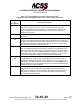
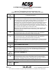
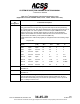
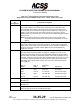
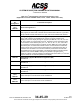
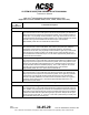
Table Of Contents
- T3CAS_Section_5
- 5 Adjustment/Test
- 1. General
- 2. Equipment
- 3. Initial Harness Checkout (New Installations Only)
- 4. System Self-Tests
- 5. Return-to-Service Test
- 6. Operational Software Loading Using an ARINC 615A Portable Data Loader or Compact Flash Card
- 7. Downloading Information from the TP3PCAS Using a CF Card
- 1. Obtain a New or Blank Compact Flash (CF) card.
- 2. Copy to the New or Blank CF card the appropriate ‘Header File’
- a) Header files are files copied to the New or Blank CF card that will instruct the computer unit what is desired to be downloaded.
- b) Header files needed to download Maintenance Data, Event Data and CRC Part Numbers can be obtained from ACSS Customer Services at +1-623-445-7070 or crc.acss@l-3com.com.
- 3. For downloading Maintenance Data, Event Data or CRC Part Numbers the aircraft does not need to be in an on-ground configuration.
- 4. Apply power to the computer unit.
- 5. Insert the CF card.
- 6. For ACSS part numbers 9005000-10000, -10101, -10202, and -10204 the DATA STATUS LED will UblinkU green once; this indicates the unit recognized that a CF card was inserted.
- 7. For ACSS part numbers 9005000-11203, -11801 and -55801 the DATA STATUS LED will UblinkU green while reading the header file and performing the action defined in the header file.
- 8. Flight Data Recording
- 1. T3CAS part numbers 9005000-10000, -10101, -10202, and -10204 only support FAT16 CF card formatting. T3CAS part numbers 9005000-11203, -11801 and -55801 support both FAT16 and FAT32 CF card formatting.
- B. Flight Data
- 1. Obtain a New or Blank CF Card.
- 2. Copy to the New or Blank CF Card the Appropriate Header File.
- 3. Header files are files copied to the New or Blank CF card that will instruct the computer unit what is desired to be downloaded.
- 4. For Flight Data Recording, the aircraft does not need to be in an on-ground configuration.
- 5. Apply power to the computer unit.
- 6. Insert the CF card.
- B. Flight Data
- 9. Downloaded Maintenance Data, Event Data And Flight Data May Be Sent To ACSS Customer Services For Analysis
- 5 Adjustment/Test
- T3CAS_Section_6
- T3CAS_Section_7
- 7 Maintenance Practices
- 1. General
- 2. Equipment and Materials
- 3. Procedure for the TP3PCAS Computer Unit
- 4. Procedure for the APM (Not applicable for part numbers 9005000-10000, -10101, -10202, -10204, or -11203)
- 5. Procedure for the Directional Antenna
- 6. Procedure for the Omnidirectional Antenna (Applicable to part numbers 9005000-11203, -11801 and -55801)
- 7. Procedure for the Control Panel
- 8. Procedure for the VSI/TRA Display
- 9. Instructions for Continued Airworthiness, FAR Part 25.1529
- 7 Maintenance Practices
- T3CAS_Section_8
- T3CAS_Section_9
- T3CAS_Section_10
- T3CAS_Appendix_A

SYSTEM DESCRIPTION AND INSTALLATION MANUAL
T
3
CAS/Part No.9005000
Table 4-1: T
3
CAS Computer Unit Interface Description (cont)
(Applicable to Part No. 9005000-10000, -10101, -10202, -10204, and -11203)
Connector
Pin
Designation
Functional Description
RBP-8A
Thru
RBP-8D
Reserved Program Pins
RBP-8E
Self-Test Test Inhibit Program Pin (NO)
This program pin determines if self-test will be inhibited while airborne. If grounded,
this pin inhibits self-test while airborne. If open, self-test is enabled while airborne.
RBP-8F
TA/RA Display Symbol Maximum 16 Program Pin (NO)
The T
3
CAS computer unit establishes the number of intruder symbols to be
displayed on the TA display through the program pins RBP-8F, -8G, -8H, -8J, and -
8K. This number can vary between 0 and 31, depending on the programming that
is a summation of the selected pins (-8F = 16, -8G = 8, -8H = 4, -8J = 2 and -8K =
1). Connecting one of these pins to program common (RBP-7K) conveys that the
associated pin is not selected and that its value is not included in the summation.
Leaving the pin open conveys that the associated pin is selected and its value is
included in the summation. The encoded number is placed within the RTS data
word (label 357) and sent to the display. The display should then limit the intruder
symbols to this number. NOTE: Although it is possible to program pin the
maximum number of intruder symbols to be displayed to be less than 8, T
3
CAS will
output a minimum of 8 intruder symbols to the display.
RBP-8G
TA/RA Display Symbol Maximum 8 Program Pin (NO)
See RBP-8F.
RBP-8H
TA/RA Display Symbol Maximum 4 Program Pin (NO)
See RBP-8F.
RBP-8J
TA/RA Display Symbol Maximum 2 Program Pin (NO)
See RBP-8F.
RBP-8K
TA/RA Display Symbol Maximum 1 Program Pin (NO)
See RBP-8F.
RBP-9A
Thru
RBP-9K
Reserved Factory Test Pins
Leave these pins unconnected for aircraft installations.
RBP-10A
Thru
RBP-10K
Reserved Factory Test Pins
Leave these pins unconnected for aircraft installations
Pub. No. 8600200-001, Revision 004
34-45-29
4-31
04 Nov 2014
Use or disclosure of information on this page is subject to the restrictions in the proprietary notice of this document.