
User's Manual
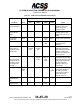
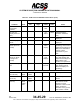
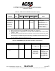
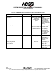
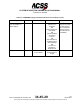
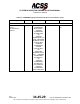
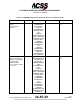
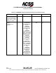
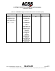
Table Of Contents
- T3CAS_Section_5
- 5 Adjustment/Test
- 1. General
- 2. Equipment
- 3. Initial Harness Checkout (New Installations Only)
- 4. System Self-Tests
- 5. Return-to-Service Test
- 6. Operational Software Loading Using an ARINC 615A Portable Data Loader or Compact Flash Card
- 7. Downloading Information from the TP3PCAS Using a CF Card
- 1. Obtain a New or Blank Compact Flash (CF) card.
- 2. Copy to the New or Blank CF card the appropriate ‘Header File’
- a) Header files are files copied to the New or Blank CF card that will instruct the computer unit what is desired to be downloaded.
- b) Header files needed to download Maintenance Data, Event Data and CRC Part Numbers can be obtained from ACSS Customer Services at +1-623-445-7070 or crc.acss@l-3com.com.
- 3. For downloading Maintenance Data, Event Data or CRC Part Numbers the aircraft does not need to be in an on-ground configuration.
- 4. Apply power to the computer unit.
- 5. Insert the CF card.
- 6. For ACSS part numbers 9005000-10000, -10101, -10202, and -10204 the DATA STATUS LED will UblinkU green once; this indicates the unit recognized that a CF card was inserted.
- 7. For ACSS part numbers 9005000-11203, -11801 and -55801 the DATA STATUS LED will UblinkU green while reading the header file and performing the action defined in the header file.
- 8. Flight Data Recording
- 1. T3CAS part numbers 9005000-10000, -10101, -10202, and -10204 only support FAT16 CF card formatting. T3CAS part numbers 9005000-11203, -11801 and -55801 support both FAT16 and FAT32 CF card formatting.
- B. Flight Data
- 1. Obtain a New or Blank CF Card.
- 2. Copy to the New or Blank CF Card the Appropriate Header File.
- 3. Header files are files copied to the New or Blank CF card that will instruct the computer unit what is desired to be downloaded.
- 4. For Flight Data Recording, the aircraft does not need to be in an on-ground configuration.
- 5. Apply power to the computer unit.
- 6. Insert the CF card.
- B. Flight Data
- 9. Downloaded Maintenance Data, Event Data And Flight Data May Be Sent To ACSS Customer Services For Analysis
- 5 Adjustment/Test
- T3CAS_Section_6
- T3CAS_Section_7
- 7 Maintenance Practices
- 1. General
- 2. Equipment and Materials
- 3. Procedure for the TP3PCAS Computer Unit
- 4. Procedure for the APM (Not applicable for part numbers 9005000-10000, -10101, -10202, -10204, or -11203)
- 5. Procedure for the Directional Antenna
- 6. Procedure for the Omnidirectional Antenna (Applicable to part numbers 9005000-11203, -11801 and -55801)
- 7. Procedure for the Control Panel
- 8. Procedure for the VSI/TRA Display
- 9. Instructions for Continued Airworthiness, FAR Part 25.1529
- 7 Maintenance Practices
- T3CAS_Section_8
- T3CAS_Section_9
- T3CAS_Section_10
- T3CAS_Appendix_A

SYSTEM DESCRIPTION AND INSTALLATION MANUAL
T
3
CAS/Part No.9005000
Table 6-1: TCAS Aural and VSI/TRA Annunciations (cont)
Condition
Aural
VSI/TRA Annunciation
Notes
Upper
Left
Upper
Right
Center
Color
TCAS EXTENDED SELF-TEST (MAINTENANCE ONLY) (Note 2, 3.)
TCAS Extended
Test Mode (Test
Switch Held at 7
Seconds for 2
Seconds and
Aircraft on the
Ground Only)
System
Informati
on pages
White
Current status of the
TCAS system
transponder antennas,
radio altimeters
barometric altitude, etc.
is presented in a series
of pages called by
selection of 4096 code.
NOTES:
1.
Self-Test should only be run in STANDBY mode in flight or on the ground.
2.
Extended Self-Test is not applicable to T
3
CAS part numbers 9005000-10000, -10101, -10202,
-10204, or -11203.
3.
Extended Self-Test provides maintenance information on seven screens selected using 4096
code. This mode is available only on the ground and in STANDBY. Extended Self-Test ends
automatically with a TCAS/Transponder mode change or if the aircraft becomes airborne. Not
all TCAS displays support this extended test mode.
(2) TAWS/RWS Display and Aural state indications and conditions.
Table 6-2: TAWS/RWS Display Aural State Indications and Conditions
Display
Color
Aural
Conditions
Notes
<Normal Operations>
(Multiple)
<Normal>
TAWS Operational
and Terrain image
is
displayed/selected
Appropriate Terrain
image is displayed
“TERR” <Normal
Operations>
(Multiple)
<Normal>
Aircraft dependent
based on the
’TAWS Mode
Display Enable’
factory option
Location of the
’TERR’ is
configurable, Color
of the ’TERR’ is
also configurable
and changes with
CPA Caution and
Warning
Pub. No. 8600200-001, Revision 004
34-45-29
6-7
04 Nov2014
Use or disclosure of information on this page is subject to the restrictions in the proprietary notice of this document.