
User's Manual
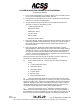
Table Of Contents
- T3CAS_Section_5
- 5 Adjustment/Test
- 1. General
- 2. Equipment
- 3. Initial Harness Checkout (New Installations Only)
- 4. System Self-Tests
- 5. Return-to-Service Test
- 6. Operational Software Loading Using an ARINC 615A Portable Data Loader or Compact Flash Card
- 7. Downloading Information from the TP3PCAS Using a CF Card
- 1. Obtain a New or Blank Compact Flash (CF) card.
- 2. Copy to the New or Blank CF card the appropriate ‘Header File’
- a) Header files are files copied to the New or Blank CF card that will instruct the computer unit what is desired to be downloaded.
- b) Header files needed to download Maintenance Data, Event Data and CRC Part Numbers can be obtained from ACSS Customer Services at +1-623-445-7070 or crc.acss@l-3com.com.
- 3. For downloading Maintenance Data, Event Data or CRC Part Numbers the aircraft does not need to be in an on-ground configuration.
- 4. Apply power to the computer unit.
- 5. Insert the CF card.
- 6. For ACSS part numbers 9005000-10000, -10101, -10202, and -10204 the DATA STATUS LED will UblinkU green once; this indicates the unit recognized that a CF card was inserted.
- 7. For ACSS part numbers 9005000-11203, -11801 and -55801 the DATA STATUS LED will UblinkU green while reading the header file and performing the action defined in the header file.
- 8. Flight Data Recording
- 1. T3CAS part numbers 9005000-10000, -10101, -10202, and -10204 only support FAT16 CF card formatting. T3CAS part numbers 9005000-11203, -11801 and -55801 support both FAT16 and FAT32 CF card formatting.
- B. Flight Data
- 1. Obtain a New or Blank CF Card.
- 2. Copy to the New or Blank CF Card the Appropriate Header File.
- 3. Header files are files copied to the New or Blank CF card that will instruct the computer unit what is desired to be downloaded.
- 4. For Flight Data Recording, the aircraft does not need to be in an on-ground configuration.
- 5. Apply power to the computer unit.
- 6. Insert the CF card.
- B. Flight Data
- 9. Downloaded Maintenance Data, Event Data And Flight Data May Be Sent To ACSS Customer Services For Analysis
- 5 Adjustment/Test
- T3CAS_Section_6
- T3CAS_Section_7
- 7 Maintenance Practices
- 1. General
- 2. Equipment and Materials
- 3. Procedure for the TP3PCAS Computer Unit
- 4. Procedure for the APM (Not applicable for part numbers 9005000-10000, -10101, -10202, -10204, or -11203)
- 5. Procedure for the Directional Antenna
- 6. Procedure for the Omnidirectional Antenna (Applicable to part numbers 9005000-11203, -11801 and -55801)
- 7. Procedure for the Control Panel
- 8. Procedure for the VSI/TRA Display
- 9. Instructions for Continued Airworthiness, FAR Part 25.1529
- 7 Maintenance Practices
- T3CAS_Section_8
- T3CAS_Section_9
- T3CAS_Section_10
- T3CAS_Appendix_A

SYSTEM DESCRIPTION AND INSTALLATION MANUAL
T
3
CAS/Part No.9005000
Upon activating the maintenance pages, the T
3
CAS unit will display the
maintenance introduction page on both the captain’s and first officer’s TAWS
displays.
While in the maintenance pages:
(a) The T
3
CAS unit will display the next maintenance page when the TAWS
flight deck self-test pushbutton/switch is active for less than or equal to 3
seconds.
(b) Subsequent activations of the TAWS flight deck self-test
pushbutton/switch will result in the T
3
CAS unit displaying the next
maintenance page.
(c) The following is a listing of extended self-test information pages available
for display:
Information Displayed
Pages
Introduction
0
Table of Contents
1
Part Numbers
2, 3, 4, 5, 6, 7, 8, 9, 10
System Test
11
ACD Options Pages
12, 13 14, 15, 16, 17, 18, 19, 20, 21,
22, 23, 24, 25
The T
3
CAS unit will exit the extended self-test when the TAWS flight deck self-
test pushbutton/switch is active for greater than 3 seconds or the aircraft
transitions from ground to air.
C. T
3
CAS Computer Unit Self-Test
The Front Panel has a test switch to initiate testing of T
3
CAS as well as LED indicators
which are used for the annunciation of internal LRU or external system faults for T
3
CAS.
The testing for T
3
CAS is initiated through the test switch on the front of the LRU. TCAS
and TAWS functions both monitor the switch and initiate a test sequence when the switch
is pressed. The test results for both functions are annunciated on their respective LED
displays.
(1) With all power off, reinstall the T
3
CAS computer unit in its mounting tray. Make
sure the TCAS control panel and display(s) are also installed.
(2) Apply aircraft power and close all applicable T
3
CAS system circuit breakers.
(3) On the TCAS control panel, set the ATC/TCAS controller mode switch to Mode S
ON.
(4) Push the push-to-test button on the T
3
CAS computer unit front panel. The test
sequence that follows should occur:
● All T
3
CAS computer unit front panel annunciators come on for a 3-second
lamp test.
Pub. No. 8600200-001, Revision 004
34-45-29
5-17
04 Nov 2014
Use or disclosure of information on this page is subject to the restrictions in the proprietary notice of this document.