
User's Manual
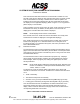
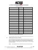
Table Of Contents
- T3CAS_Section_5
- 5 Adjustment/Test
- 1. General
- 2. Equipment
- 3. Initial Harness Checkout (New Installations Only)
- 4. System Self-Tests
- 5. Return-to-Service Test
- 6. Operational Software Loading Using an ARINC 615A Portable Data Loader or Compact Flash Card
- 7. Downloading Information from the TP3PCAS Using a CF Card
- 1. Obtain a New or Blank Compact Flash (CF) card.
- 2. Copy to the New or Blank CF card the appropriate ‘Header File’
- a) Header files are files copied to the New or Blank CF card that will instruct the computer unit what is desired to be downloaded.
- b) Header files needed to download Maintenance Data, Event Data and CRC Part Numbers can be obtained from ACSS Customer Services at +1-623-445-7070 or crc.acss@l-3com.com.
- 3. For downloading Maintenance Data, Event Data or CRC Part Numbers the aircraft does not need to be in an on-ground configuration.
- 4. Apply power to the computer unit.
- 5. Insert the CF card.
- 6. For ACSS part numbers 9005000-10000, -10101, -10202, and -10204 the DATA STATUS LED will UblinkU green once; this indicates the unit recognized that a CF card was inserted.
- 7. For ACSS part numbers 9005000-11203, -11801 and -55801 the DATA STATUS LED will UblinkU green while reading the header file and performing the action defined in the header file.
- 8. Flight Data Recording
- 1. T3CAS part numbers 9005000-10000, -10101, -10202, and -10204 only support FAT16 CF card formatting. T3CAS part numbers 9005000-11203, -11801 and -55801 support both FAT16 and FAT32 CF card formatting.
- B. Flight Data
- 1. Obtain a New or Blank CF Card.
- 2. Copy to the New or Blank CF Card the Appropriate Header File.
- 3. Header files are files copied to the New or Blank CF card that will instruct the computer unit what is desired to be downloaded.
- 4. For Flight Data Recording, the aircraft does not need to be in an on-ground configuration.
- 5. Apply power to the computer unit.
- 6. Insert the CF card.
- B. Flight Data
- 9. Downloaded Maintenance Data, Event Data And Flight Data May Be Sent To ACSS Customer Services For Analysis
- 5 Adjustment/Test
- T3CAS_Section_6
- T3CAS_Section_7
- 7 Maintenance Practices
- 1. General
- 2. Equipment and Materials
- 3. Procedure for the TP3PCAS Computer Unit
- 4. Procedure for the APM (Not applicable for part numbers 9005000-10000, -10101, -10202, -10204, or -11203)
- 5. Procedure for the Directional Antenna
- 6. Procedure for the Omnidirectional Antenna (Applicable to part numbers 9005000-11203, -11801 and -55801)
- 7. Procedure for the Control Panel
- 8. Procedure for the VSI/TRA Display
- 9. Instructions for Continued Airworthiness, FAR Part 25.1529
- 7 Maintenance Practices
- T3CAS_Section_8
- T3CAS_Section_9
- T3CAS_Section_10
- T3CAS_Appendix_A

SYSTEM DESCRIPTION AND INSTALLATION MANUAL
T
3
CAS/Part No.9005000
Push and hold the TEST button/switch on the ATC/TCAS controller for a few
seconds to start the test. When the test mode becomes active, the words “TCAS
Test” are transmitted once aurally. In addition to the TCAS test pattern, RA
indications and a white (some displays may be red) TCAS TEST annunciation
are displayed on the applicable display(s). Refer to Figure 1-17 for a typical test
pattern display on the VSI/TRA.
At the completion of the test (8 seconds), the words “TCAS Test Pass” should be
transmitted once aurally. In addition, the test pattern is removed from the
display(s) and a TCAS PASS annunciation is displayed.
NOTE:
Not all displays will annunciate “TCAS PASS”.
If the test fails, the words “TCAS Test Fail” are transmitted once aurally and a
TCAS FAIL annunciation is displayed on the applicable display(s).
If the TCAS short test fails, do the TCAS Computer Unit Self-Test procedures
referenced in paragraph 4.C. to determine which LRU or subsystem is not
functioning properly. To troubleshoot the system, refer to the procedures in the
FAULT ISOLATION section.
(2) Extended Test Mode
The extended test mode provides a flight deck initiated test that displays various
pages of text information that is selected by the ATC Mode S control panel 4096
code switches. This test mode is accessible only when on the ground and cannot
be initiated while airborne.
The extended test mode is used for maintenance purposes only. It displays
various pages of text information containing the TCAS software part number,
fault messages, status of program pins, analog and digital inputs, and other
aircraft parameters.
NOTE:
Not all TCAS displays support this extended test mode. Extended Test
mode is not enabled for T
3
CAS part numbers 9005000-10000, -10101,
-10202, -10204, or -11203.
To start the test, push and hold the TEST button/switch on the ATC/TCAS
controller for a minimum of 9 seconds. In addition the conditions that follow must
occur:
● TCAS is in Standby
● The selected transponder is in Standby
● Aircraft is on the ground (The AIR/GND discrete [RMP-5K] is grounded)
● Landing gear is extended (Landing Gear discrete [RMP-13F] is grounded).
Once the extended test mode is established, the 4096 code switches on the
ATC/TCAS controller are used to select the desired maintenance page for
display. Table 5-3 lists the extended mode page names and numbers and the
corresponding 4096 Ident Code number.
Table 5-3: Extended Test Menu Selections
5-4
04 Nov 2014
34-45-29
Pub. No. 8600200-001, Revision 004
Use or disclosure of information on this page is subject to the restrictions in the proprietary notice of this document.