
User's Manual
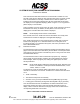
Table Of Contents
- T3CAS_Section_5
- 5 Adjustment/Test
- 1. General
- 2. Equipment
- 3. Initial Harness Checkout (New Installations Only)
- 4. System Self-Tests
- 5. Return-to-Service Test
- 6. Operational Software Loading Using an ARINC 615A Portable Data Loader or Compact Flash Card
- 7. Downloading Information from the TP3PCAS Using a CF Card
- 1. Obtain a New or Blank Compact Flash (CF) card.
- 2. Copy to the New or Blank CF card the appropriate ‘Header File’
- a) Header files are files copied to the New or Blank CF card that will instruct the computer unit what is desired to be downloaded.
- b) Header files needed to download Maintenance Data, Event Data and CRC Part Numbers can be obtained from ACSS Customer Services at +1-623-445-7070 or crc.acss@l-3com.com.
- 3. For downloading Maintenance Data, Event Data or CRC Part Numbers the aircraft does not need to be in an on-ground configuration.
- 4. Apply power to the computer unit.
- 5. Insert the CF card.
- 6. For ACSS part numbers 9005000-10000, -10101, -10202, and -10204 the DATA STATUS LED will UblinkU green once; this indicates the unit recognized that a CF card was inserted.
- 7. For ACSS part numbers 9005000-11203, -11801 and -55801 the DATA STATUS LED will UblinkU green while reading the header file and performing the action defined in the header file.
- 8. Flight Data Recording
- 1. T3CAS part numbers 9005000-10000, -10101, -10202, and -10204 only support FAT16 CF card formatting. T3CAS part numbers 9005000-11203, -11801 and -55801 support both FAT16 and FAT32 CF card formatting.
- B. Flight Data
- 1. Obtain a New or Blank CF Card.
- 2. Copy to the New or Blank CF Card the Appropriate Header File.
- 3. Header files are files copied to the New or Blank CF card that will instruct the computer unit what is desired to be downloaded.
- 4. For Flight Data Recording, the aircraft does not need to be in an on-ground configuration.
- 5. Apply power to the computer unit.
- 6. Insert the CF card.
- B. Flight Data
- 9. Downloaded Maintenance Data, Event Data And Flight Data May Be Sent To ACSS Customer Services For Analysis
- 5 Adjustment/Test
- T3CAS_Section_6
- T3CAS_Section_7
- 7 Maintenance Practices
- 1. General
- 2. Equipment and Materials
- 3. Procedure for the TP3PCAS Computer Unit
- 4. Procedure for the APM (Not applicable for part numbers 9005000-10000, -10101, -10202, -10204, or -11203)
- 5. Procedure for the Directional Antenna
- 6. Procedure for the Omnidirectional Antenna (Applicable to part numbers 9005000-11203, -11801 and -55801)
- 7. Procedure for the Control Panel
- 8. Procedure for the VSI/TRA Display
- 9. Instructions for Continued Airworthiness, FAR Part 25.1529
- 7 Maintenance Practices
- T3CAS_Section_8
- T3CAS_Section_9
- T3CAS_Section_10
- T3CAS_Appendix_A

SYSTEM DESCRIPTION AND INSTALLATION MANUAL
T
3
CAS/Part No.9005000
● 01 = Invalid light curve setting specified at power-up
● 03 = Bad checksum detected at power-up
● 04 = Illegal op-code test failed
● 05 = Unsupported test failed.
(4) Strobes the watchdog timer to keep the red X and status displayed.
NOTE:
If the ACSS VSI/TRA displays error code 10, 11, 12, 29, 30, 31, or 40 an
internal ACSS VSI/TRA failure has been detected.
Figure 5-1: VSI/TRA Fault Warning Display
4. System Self-Tests
A. TCAS Flight Deck Display Test Modes
The T
3
CAS TCAS System provides two types of test modes; a short functional test mode
and an extended maintenance test. Both test modes can be activated by the TEST button
or switch on the ATC/TCAS Control Panel. The short test mode can also be activated by
an Onboard Maintenance System (OMS) or a central fault display interface unit (CFDIU).
The extended test mode can only be initiated at the end of the short test. The short test
mode is inhibited in the air if the Self-Test Inhibit programming pin (RBP-8E) is grounded.
(1) Short Test Mode
The short test mode provides a flight deck initiated functional test of the TCAS
RA and TA displays and associated TCAS interfaces. It also provides an aural
annunciation of the TCAS system status.
The short test mode is available in all TCAS operational modes (Standby, TA
Only, or TA/RA) when on the ground. If a TA or RA occurs while airborne, the
test is terminated and normal operating status is resumed. The test mode is also
terminated if any of the Advisory Inhibit discrete inputs (grounds) are received on
pins RBP-5A, RBP-5B, RBP-5C, or RBP-5D.
Pub. No. 8600200-001, Revision 004
34-45-29
5-3
04 Nov 2014
Use or disclosure of information on this page is subject to the restrictions in the proprietary notice of this document.