
User's Manual
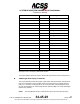
Table Of Contents
- T3CAS_Section_5
- 5 Adjustment/Test
- 1. General
- 2. Equipment
- 3. Initial Harness Checkout (New Installations Only)
- 4. System Self-Tests
- 5. Return-to-Service Test
- 6. Operational Software Loading Using an ARINC 615A Portable Data Loader or Compact Flash Card
- 7. Downloading Information from the TP3PCAS Using a CF Card
- 1. Obtain a New or Blank Compact Flash (CF) card.
- 2. Copy to the New or Blank CF card the appropriate ‘Header File’
- a) Header files are files copied to the New or Blank CF card that will instruct the computer unit what is desired to be downloaded.
- b) Header files needed to download Maintenance Data, Event Data and CRC Part Numbers can be obtained from ACSS Customer Services at +1-623-445-7070 or crc.acss@l-3com.com.
- 3. For downloading Maintenance Data, Event Data or CRC Part Numbers the aircraft does not need to be in an on-ground configuration.
- 4. Apply power to the computer unit.
- 5. Insert the CF card.
- 6. For ACSS part numbers 9005000-10000, -10101, -10202, and -10204 the DATA STATUS LED will UblinkU green once; this indicates the unit recognized that a CF card was inserted.
- 7. For ACSS part numbers 9005000-11203, -11801 and -55801 the DATA STATUS LED will UblinkU green while reading the header file and performing the action defined in the header file.
- 8. Flight Data Recording
- 1. T3CAS part numbers 9005000-10000, -10101, -10202, and -10204 only support FAT16 CF card formatting. T3CAS part numbers 9005000-11203, -11801 and -55801 support both FAT16 and FAT32 CF card formatting.
- B. Flight Data
- 1. Obtain a New or Blank CF Card.
- 2. Copy to the New or Blank CF Card the Appropriate Header File.
- 3. Header files are files copied to the New or Blank CF card that will instruct the computer unit what is desired to be downloaded.
- 4. For Flight Data Recording, the aircraft does not need to be in an on-ground configuration.
- 5. Apply power to the computer unit.
- 6. Insert the CF card.
- B. Flight Data
- 9. Downloaded Maintenance Data, Event Data And Flight Data May Be Sent To ACSS Customer Services For Analysis
- 5 Adjustment/Test
- T3CAS_Section_6
- T3CAS_Section_7
- 7 Maintenance Practices
- 1. General
- 2. Equipment and Materials
- 3. Procedure for the TP3PCAS Computer Unit
- 4. Procedure for the APM (Not applicable for part numbers 9005000-10000, -10101, -10202, -10204, or -11203)
- 5. Procedure for the Directional Antenna
- 6. Procedure for the Omnidirectional Antenna (Applicable to part numbers 9005000-11203, -11801 and -55801)
- 7. Procedure for the Control Panel
- 8. Procedure for the VSI/TRA Display
- 9. Instructions for Continued Airworthiness, FAR Part 25.1529
- 7 Maintenance Practices
- T3CAS_Section_8
- T3CAS_Section_9
- T3CAS_Section_10
- T3CAS_Appendix_A

SYSTEM DESCRIPTION AND INSTALLATION MANUAL
T
3
CAS/Part No.9005000
Table 5-2: Computer Unit Harness Checkout
Connector Pin No.
Pin Function
P1C-1 (LBP)
115 V ac (H) T
3
CAS Power
P1C-5 (LBP)
115 V ac (H) External Fan
P1C-10 (LBP)
28 V dc T
3
CAS Power
B. T
3
CAS Controller and Display Unit Harness Checkout
Refer to the applicable controller and display unit interconnect diagrams to do continuity
measurements and to ensure confidence in wiring for these units.
C. LRU Pre-installation Power Checkout
Before you do any operational tests, a power-on check is recommended to reduce the
possibility of damage to newly installed system components due to miswired power
leads.
(1) Make sure all T
3
CAS system components are removed from their mounting trays
or that their aircraft mating connector(s) are disconnected.
(2) Connect external power to aircraft.
(3) Close all T
3
CAS system 115-volt, 400-Hz circuit breakers, if applicable, and
check for 115 volts ac at the appropriate LRU mating connector pins. Refer to the
applicable interconnect diagrams for LRU pin numbers.
(4) If power is misapplied on any connector pin, open the circuit breaker and rework
miswired harness.
(5) Remove aircraft power.
D. Initial System Installation Operational Test
The initial checkout of a newly installed system should start with a system self-test and
then be followed by a ramp test. The system self-test procedures are referenced in
paragraph 4.A. The ramp tests should include a Scenario Test and a Power and
Frequency Test. Refer to the applicable TCAS/Transponder Ramp Tester Operation
Manual for procedures to do these tests.
If an ACSS VSI/TRA is used as the display instrument, it contains a feature that displays
some typical installation errors. See Figure 5-1. If an error is detected during initial
installation checkout, the VSI/TRA displays the error as follows:
(1) Removes all symbology from the display
(2) Displays a red X that covers the entire screen
(3) Displays a two-digit error code as follows:
● 00 = Invalid discrete setting at power-up
5-2
04 Nov 2014
34-45-29
Pub. No. 8600200-001, Revision 004
Use or disclosure of information on this page is subject to the restrictions in the proprietary notice of this document.