
User's Manual
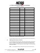
Table Of Contents
- T3CAS_Section_5
- 5 Adjustment/Test
- 1. General
- 2. Equipment
- 3. Initial Harness Checkout (New Installations Only)
- 4. System Self-Tests
- 5. Return-to-Service Test
- 6. Operational Software Loading Using an ARINC 615A Portable Data Loader or Compact Flash Card
- 7. Downloading Information from the TP3PCAS Using a CF Card
- 1. Obtain a New or Blank Compact Flash (CF) card.
- 2. Copy to the New or Blank CF card the appropriate ‘Header File’
- a) Header files are files copied to the New or Blank CF card that will instruct the computer unit what is desired to be downloaded.
- b) Header files needed to download Maintenance Data, Event Data and CRC Part Numbers can be obtained from ACSS Customer Services at +1-623-445-7070 or crc.acss@l-3com.com.
- 3. For downloading Maintenance Data, Event Data or CRC Part Numbers the aircraft does not need to be in an on-ground configuration.
- 4. Apply power to the computer unit.
- 5. Insert the CF card.
- 6. For ACSS part numbers 9005000-10000, -10101, -10202, and -10204 the DATA STATUS LED will UblinkU green once; this indicates the unit recognized that a CF card was inserted.
- 7. For ACSS part numbers 9005000-11203, -11801 and -55801 the DATA STATUS LED will UblinkU green while reading the header file and performing the action defined in the header file.
- 8. Flight Data Recording
- 1. T3CAS part numbers 9005000-10000, -10101, -10202, and -10204 only support FAT16 CF card formatting. T3CAS part numbers 9005000-11203, -11801 and -55801 support both FAT16 and FAT32 CF card formatting.
- B. Flight Data
- 1. Obtain a New or Blank CF Card.
- 2. Copy to the New or Blank CF Card the Appropriate Header File.
- 3. Header files are files copied to the New or Blank CF card that will instruct the computer unit what is desired to be downloaded.
- 4. For Flight Data Recording, the aircraft does not need to be in an on-ground configuration.
- 5. Apply power to the computer unit.
- 6. Insert the CF card.
- B. Flight Data
- 9. Downloaded Maintenance Data, Event Data And Flight Data May Be Sent To ACSS Customer Services For Analysis
- 5 Adjustment/Test
- T3CAS_Section_6
- T3CAS_Section_7
- 7 Maintenance Practices
- 1. General
- 2. Equipment and Materials
- 3. Procedure for the TP3PCAS Computer Unit
- 4. Procedure for the APM (Not applicable for part numbers 9005000-10000, -10101, -10202, -10204, or -11203)
- 5. Procedure for the Directional Antenna
- 6. Procedure for the Omnidirectional Antenna (Applicable to part numbers 9005000-11203, -11801 and -55801)
- 7. Procedure for the Control Panel
- 8. Procedure for the VSI/TRA Display
- 9. Instructions for Continued Airworthiness, FAR Part 25.1529
- 7 Maintenance Practices
- T3CAS_Section_8
- T3CAS_Section_9
- T3CAS_Section_10
- T3CAS_Appendix_A

SYSTEM DESCRIPTION AND INSTALLATION MANUAL
T
3
CAS/Part No.9005000
ADJUSTMENT/TEST
1. General
The procedures that follow are designed to check for proper operation and satisfactory installation
of the T
3
CAS Integrated Platform system components.
Should any failures occur while performing the check out procedures, refer to FAULT ISOLATION
as required.
2. Equipment
See Table 5-1 for equipment required to test the unit.
Table 5-1: Equipment
Name
Description
Source
Digital Multimeter
Fluke Model 29 Digital Multimeter
John Fluke Mfg Co Inc,
Everett, WA
TCAS Ramp Tester
TCAS-201 Reply Generator
Traffic Alert and Collision
Avoidance System Test Set
Aeroflex, Inc.
Plainview, NY
XPDR Ramp Tester
ATC-601 Mode S/A/C
Transponder Ramp Test Set
Aeroflex, Inc.
Plainview, NY
TCAS/XPDR Ramp Tester
IFR-6000 Ramp Test Set
Aeroflex, Inc.
Plainview, NY
NOTE:
Equivalent alternatives are permitted for equipment in this list.
3. Initial Harness Checkout (New Installations Only)
A. T
3
CAS Computer Unit Harness Checkout
Check the T
3
CAS computer unit’s mounting tray connector pins referenced in Table 5-2,
to make sure they are not connected or shorted to ground. A ground on these pins can
cause damage or degrade system performance.
Pub. No. 8600200-001, Revision 004
34-45-29
5-1
04 Nov 2014
Use or disclosure of information on this page is subject to the restrictions in the proprietary notice of this document.