
User's Manual
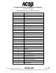
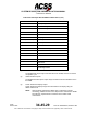
Table Of Contents
- T3CAS_Section_5
- 5 Adjustment/Test
- 1. General
- 2. Equipment
- 3. Initial Harness Checkout (New Installations Only)
- 4. System Self-Tests
- 5. Return-to-Service Test
- 6. Operational Software Loading Using an ARINC 615A Portable Data Loader or Compact Flash Card
- 7. Downloading Information from the TP3PCAS Using a CF Card
- 1. Obtain a New or Blank Compact Flash (CF) card.
- 2. Copy to the New or Blank CF card the appropriate ‘Header File’
- a) Header files are files copied to the New or Blank CF card that will instruct the computer unit what is desired to be downloaded.
- b) Header files needed to download Maintenance Data, Event Data and CRC Part Numbers can be obtained from ACSS Customer Services at +1-623-445-7070 or crc.acss@l-3com.com.
- 3. For downloading Maintenance Data, Event Data or CRC Part Numbers the aircraft does not need to be in an on-ground configuration.
- 4. Apply power to the computer unit.
- 5. Insert the CF card.
- 6. For ACSS part numbers 9005000-10000, -10101, -10202, and -10204 the DATA STATUS LED will UblinkU green once; this indicates the unit recognized that a CF card was inserted.
- 7. For ACSS part numbers 9005000-11203, -11801 and -55801 the DATA STATUS LED will UblinkU green while reading the header file and performing the action defined in the header file.
- 8. Flight Data Recording
- 1. T3CAS part numbers 9005000-10000, -10101, -10202, and -10204 only support FAT16 CF card formatting. T3CAS part numbers 9005000-11203, -11801 and -55801 support both FAT16 and FAT32 CF card formatting.
- B. Flight Data
- 1. Obtain a New or Blank CF Card.
- 2. Copy to the New or Blank CF Card the Appropriate Header File.
- 3. Header files are files copied to the New or Blank CF card that will instruct the computer unit what is desired to be downloaded.
- 4. For Flight Data Recording, the aircraft does not need to be in an on-ground configuration.
- 5. Apply power to the computer unit.
- 6. Insert the CF card.
- B. Flight Data
- 9. Downloaded Maintenance Data, Event Data And Flight Data May Be Sent To ACSS Customer Services For Analysis
- 5 Adjustment/Test
- T3CAS_Section_6
- T3CAS_Section_7
- 7 Maintenance Practices
- 1. General
- 2. Equipment and Materials
- 3. Procedure for the TP3PCAS Computer Unit
- 4. Procedure for the APM (Not applicable for part numbers 9005000-10000, -10101, -10202, -10204, or -11203)
- 5. Procedure for the Directional Antenna
- 6. Procedure for the Omnidirectional Antenna (Applicable to part numbers 9005000-11203, -11801 and -55801)
- 7. Procedure for the Control Panel
- 8. Procedure for the VSI/TRA Display
- 9. Instructions for Continued Airworthiness, FAR Part 25.1529
- 7 Maintenance Practices
- T3CAS_Section_8
- T3CAS_Section_9
- T3CAS_Section_10
- T3CAS_Appendix_A

SYSTEM DESCRIPTION AND INSTALLATION MANUAL
T
3
CAS/Part No.9005000
(11) Altitude Callout Disable
The Altitude Callout Disable Discrete input is used to disable all altitude callouts.
NOTE:
Altitude callouts are not applicable for part numbers 9005000-10000, -
10101, -10202, -10204, and -11203.
(12) Engine Out
When set, the Engine Out discrete indicates that one or more aircraft engines is
inoperative. The Engine Out data is used as part of the aircraft performance
calculations during a TAWS event.
(13) Audio Inhibit
Audio inhibits all audio until the ground state is transitioned.
(14) GPWS Inhibit Switch
Inhibits GPWS Modes aural alert annunciation.
(15) Terrain Display Select #1 and #2 Momentary Switch (Capt and FO “TERR ON
ND” Pushbutton)
NOTE:
Cockpit name may differ by installation.
State Transition Initiated to Display/Not Display Terrain Image on the ND. This is
a “momentary” discrete input.
(16) Momentary Audio Inhibit
Inhibits TAWS Audio Output for current alert only.
(17) WXR Radar #1 and 2 On/Off
Weather Radar On/Off discrete input.
(18) Simulator Reposition
Enables operation in a simulator environment to allow operations such as
parameter freeze, rapid relocation, or repositioning thus avoiding filtering.
G. TAWS/RWS and Transponder Digital Output Data
(1) GCAM Event Data
The T
3
CAS TAWS events are caused by terrain and weather conditions. An
event begins when a terrain or weather condition causes the T
3
CAS to declare a
TAWS caution or warning alert or when the aircraft telemetry causes a Bank
Angle Callout. This data is recorded each time an alert occurs (caution or
warning) and contains information about the triggering event. The T
3
CAS then
transmits the GCAM Event Data over one of the programmable ARINC 429
output busses in 10.
Table 4-58 shows the GCAM Event Data Labels transmitted on the A429 output
Bus.
4-156
04 Nov 2014
34-45-29
Pub. No. 8600200-001, Revision 004
Use or disclosure of information on this page is subject to the restrictions in the proprietary notice of this document.