
User's Manual
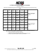
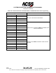
Table Of Contents
- T3CAS_Section_5
- 5 Adjustment/Test
- 1. General
- 2. Equipment
- 3. Initial Harness Checkout (New Installations Only)
- 4. System Self-Tests
- 5. Return-to-Service Test
- 6. Operational Software Loading Using an ARINC 615A Portable Data Loader or Compact Flash Card
- 7. Downloading Information from the TP3PCAS Using a CF Card
- 1. Obtain a New or Blank Compact Flash (CF) card.
- 2. Copy to the New or Blank CF card the appropriate ‘Header File’
- a) Header files are files copied to the New or Blank CF card that will instruct the computer unit what is desired to be downloaded.
- b) Header files needed to download Maintenance Data, Event Data and CRC Part Numbers can be obtained from ACSS Customer Services at +1-623-445-7070 or crc.acss@l-3com.com.
- 3. For downloading Maintenance Data, Event Data or CRC Part Numbers the aircraft does not need to be in an on-ground configuration.
- 4. Apply power to the computer unit.
- 5. Insert the CF card.
- 6. For ACSS part numbers 9005000-10000, -10101, -10202, and -10204 the DATA STATUS LED will UblinkU green once; this indicates the unit recognized that a CF card was inserted.
- 7. For ACSS part numbers 9005000-11203, -11801 and -55801 the DATA STATUS LED will UblinkU green while reading the header file and performing the action defined in the header file.
- 8. Flight Data Recording
- 1. T3CAS part numbers 9005000-10000, -10101, -10202, and -10204 only support FAT16 CF card formatting. T3CAS part numbers 9005000-11203, -11801 and -55801 support both FAT16 and FAT32 CF card formatting.
- B. Flight Data
- 1. Obtain a New or Blank CF Card.
- 2. Copy to the New or Blank CF Card the Appropriate Header File.
- 3. Header files are files copied to the New or Blank CF card that will instruct the computer unit what is desired to be downloaded.
- 4. For Flight Data Recording, the aircraft does not need to be in an on-ground configuration.
- 5. Apply power to the computer unit.
- 6. Insert the CF card.
- B. Flight Data
- 9. Downloaded Maintenance Data, Event Data And Flight Data May Be Sent To ACSS Customer Services For Analysis
- 5 Adjustment/Test
- T3CAS_Section_6
- T3CAS_Section_7
- 7 Maintenance Practices
- 1. General
- 2. Equipment and Materials
- 3. Procedure for the TP3PCAS Computer Unit
- 4. Procedure for the APM (Not applicable for part numbers 9005000-10000, -10101, -10202, -10204, or -11203)
- 5. Procedure for the Directional Antenna
- 6. Procedure for the Omnidirectional Antenna (Applicable to part numbers 9005000-11203, -11801 and -55801)
- 7. Procedure for the Control Panel
- 8. Procedure for the VSI/TRA Display
- 9. Instructions for Continued Airworthiness, FAR Part 25.1529
- 7 Maintenance Practices
- T3CAS_Section_8
- T3CAS_Section_9
- T3CAS_Section_10
- T3CAS_Appendix_A

SYSTEM DESCRIPTION AND INSTALLATION MANUAL
T
3
CAS/Part No.9005000
The minimum External Sensor input accuracy accepted for True Track Angle is 1
degree from a primary source (GPS/FMS) and 5 degrees from a secondary
(Inertial) source.
(4) Radio Altitude (Digital/Analog)
T
3
CAS accepts up to 3 analog Radio Altitude inputs or 3 Digital ARINC 429
Radio Altitude inputs. Digital Radio Altitude Inputs 1 and 2 are shared with the
TCAS function. TAWS, TCAS and RWS require the Radio altitude input.
Radio altimeter equipment interfacing with T
3
CAS must be compliant with TSO-
C87 Airborne Low-Range Radio Altimeter, ETSO-2C87, Low Range Radio
Altimeters, or RTCA DO-155, Minimum Performance Standards Airborne Low-
Range Radar Altimeters.
The external LRUs/External Sensors providing the data parameters must provide
an input to the T
3
CAS that is within the range of ±3 feet (0.914 meters) or 4%
from 0 to 500 feet (152.4 meters) and 5% when above 500 feet (152.4 meters).
The electrical pin connections for the Digital/Analog Radio Altitude is listed under
Table 4-1 and Table 4-2 of sub-section 2 T
3
CAS Interface Description.
(a) Digital Input
The Table below shows the ARINC 429 digital interface characteristics
for the ARINC 707 radio altimeter system. Two of the ARINC 429 input
busses (RADIO_ALTITUDE_1 and RADIO_ALTITUDE_2) are shared
with the TCAS ARINC 429 Radio Altitude Inputs. The TAWS input
circuitry is independent from TCAS. (See Table 4-54.)
Table 4-54: Radio Altitude
429 Label: 164 Octal
Units: Feet
Max Range: ±8,192 Feet
Approx. LSB: 0.125
Data Bits:16
13(lsb) – 28(msb)
Sign Bit:29
0 = Up, 1 = Down
Pad Bits: 11, 12
Transmit Interval:
25-50 ms
Data Type: Two’s
Complement Binary
(b) Analog Input
The Analog Radio Altitude inputs are compatible with an ARINC 552
Radio Altimeter system and may have a number of different input
formats as defined for specific aircraft requirements. The external
connector pins for Analog Radio Altitude Inputs #1 and #2 are shared by
TCAS and TAWS/RWS, both have independent circuitry.
The following common mode and differential mode inputs signals are
accepted by the T
3
CAS with the voltage ranges defined:
● (+) input common mode range -5.0 to +40.0 V dc
● (-) input common mode range -2.5 to +2.5 V dc
● Differential (+ to -) range -2.5 to +37.5 V dc
Pub. No. 8600200-001, Revision 004
34-45-29
4-147
04 Nov 2014
Use or disclosure of information on this page is subject to the restrictions in the proprietary notice of this document.