
User's Manual
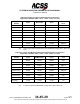
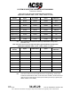
Table Of Contents
- T3CAS_Section_5
- 5 Adjustment/Test
- 1. General
- 2. Equipment
- 3. Initial Harness Checkout (New Installations Only)
- 4. System Self-Tests
- 5. Return-to-Service Test
- 6. Operational Software Loading Using an ARINC 615A Portable Data Loader or Compact Flash Card
- 7. Downloading Information from the TP3PCAS Using a CF Card
- 1. Obtain a New or Blank Compact Flash (CF) card.
- 2. Copy to the New or Blank CF card the appropriate ‘Header File’
- a) Header files are files copied to the New or Blank CF card that will instruct the computer unit what is desired to be downloaded.
- b) Header files needed to download Maintenance Data, Event Data and CRC Part Numbers can be obtained from ACSS Customer Services at +1-623-445-7070 or crc.acss@l-3com.com.
- 3. For downloading Maintenance Data, Event Data or CRC Part Numbers the aircraft does not need to be in an on-ground configuration.
- 4. Apply power to the computer unit.
- 5. Insert the CF card.
- 6. For ACSS part numbers 9005000-10000, -10101, -10202, and -10204 the DATA STATUS LED will UblinkU green once; this indicates the unit recognized that a CF card was inserted.
- 7. For ACSS part numbers 9005000-11203, -11801 and -55801 the DATA STATUS LED will UblinkU green while reading the header file and performing the action defined in the header file.
- 8. Flight Data Recording
- 1. T3CAS part numbers 9005000-10000, -10101, -10202, and -10204 only support FAT16 CF card formatting. T3CAS part numbers 9005000-11203, -11801 and -55801 support both FAT16 and FAT32 CF card formatting.
- B. Flight Data
- 1. Obtain a New or Blank CF Card.
- 2. Copy to the New or Blank CF Card the Appropriate Header File.
- 3. Header files are files copied to the New or Blank CF card that will instruct the computer unit what is desired to be downloaded.
- 4. For Flight Data Recording, the aircraft does not need to be in an on-ground configuration.
- 5. Apply power to the computer unit.
- 6. Insert the CF card.
- B. Flight Data
- 9. Downloaded Maintenance Data, Event Data And Flight Data May Be Sent To ACSS Customer Services For Analysis
- 5 Adjustment/Test
- T3CAS_Section_6
- T3CAS_Section_7
- 7 Maintenance Practices
- 1. General
- 2. Equipment and Materials
- 3. Procedure for the TP3PCAS Computer Unit
- 4. Procedure for the APM (Not applicable for part numbers 9005000-10000, -10101, -10202, -10204, or -11203)
- 5. Procedure for the Directional Antenna
- 6. Procedure for the Omnidirectional Antenna (Applicable to part numbers 9005000-11203, -11801 and -55801)
- 7. Procedure for the Control Panel
- 8. Procedure for the VSI/TRA Display
- 9. Instructions for Continued Airworthiness, FAR Part 25.1529
- 7 Maintenance Practices
- T3CAS_Section_8
- T3CAS_Section_9
- T3CAS_Section_10
- T3CAS_Appendix_A

SYSTEM DESCRIPTION AND INSTALLATION MANUAL
T
3
CAS/Part No.9005000
Table 4-44: Aircraft Altitude Limit
Pin
Description
Connected to:
RMP 6E
2000 ft (609.6 m)
1 = Connected to RMP – 6 K
0 = Open
RMP 6F
4000 ft (1219.2 m)
RMP 6G
8000 ft (2438.4 m)
RMP 6H
16000 ft (4876.8 m)
RMP 6J
32000 ft (9753.6 m)
(26) This section defines the Display All Traffic Pin Programming.
Table 4-45: Display All Traffic
Configuration
Number
Description
Connect RBP- 7F to:
1
Display all traffic
Open
2
Display TA or RA
RBP-7K
(27) This section defines the TA/RA Display Intruder Limit. These 5 program pin
inputs are used to encode the maximum number of intruder symbols to be
presented on TA/RA displays. The logic of programming is that an “Open”
represents “Selected” and a connection to Program Pin Common RBP-7K
represents “Not Selected.” A minimum of 8 intruders are displayed, even though
a value for less than 8 intruders can be selected.
Table 4-46: TA/RA Display Intruder
Pin
Description
Connected to:
RBP 8F
16 intruders
RBP 7K = Not selected
Open = Selected
RBP 8G
8 intruders
RBP 8H
4 intruders
RBP 8J
2 intruders
RBP 8K
1 intruder
(28) This section defines the RA Valid Disable Pin Programming.
Table 4-47: RA Valid Disable
Monitoring of valid discretes
from RA indicators
Connect RBP 4G to:
Disable
RBP 7K
Enable
Open
Pub. No. 8600200-001, Revision 004
34-45-29
4-139
04 Nov 2014
Use or disclosure of information on this page is subject to the restrictions in the proprietary notice of this document.