
User's Manual
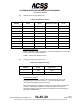
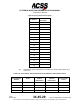
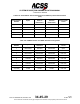
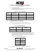
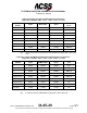
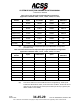
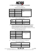
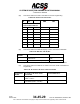
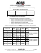
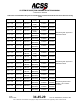
Table Of Contents
- T3CAS_Section_5
- 5 Adjustment/Test
- 1. General
- 2. Equipment
- 3. Initial Harness Checkout (New Installations Only)
- 4. System Self-Tests
- 5. Return-to-Service Test
- 6. Operational Software Loading Using an ARINC 615A Portable Data Loader or Compact Flash Card
- 7. Downloading Information from the TP3PCAS Using a CF Card
- 1. Obtain a New or Blank Compact Flash (CF) card.
- 2. Copy to the New or Blank CF card the appropriate ‘Header File’
- a) Header files are files copied to the New or Blank CF card that will instruct the computer unit what is desired to be downloaded.
- b) Header files needed to download Maintenance Data, Event Data and CRC Part Numbers can be obtained from ACSS Customer Services at +1-623-445-7070 or crc.acss@l-3com.com.
- 3. For downloading Maintenance Data, Event Data or CRC Part Numbers the aircraft does not need to be in an on-ground configuration.
- 4. Apply power to the computer unit.
- 5. Insert the CF card.
- 6. For ACSS part numbers 9005000-10000, -10101, -10202, and -10204 the DATA STATUS LED will UblinkU green once; this indicates the unit recognized that a CF card was inserted.
- 7. For ACSS part numbers 9005000-11203, -11801 and -55801 the DATA STATUS LED will UblinkU green while reading the header file and performing the action defined in the header file.
- 8. Flight Data Recording
- 1. T3CAS part numbers 9005000-10000, -10101, -10202, and -10204 only support FAT16 CF card formatting. T3CAS part numbers 9005000-11203, -11801 and -55801 support both FAT16 and FAT32 CF card formatting.
- B. Flight Data
- 1. Obtain a New or Blank CF Card.
- 2. Copy to the New or Blank CF Card the Appropriate Header File.
- 3. Header files are files copied to the New or Blank CF card that will instruct the computer unit what is desired to be downloaded.
- 4. For Flight Data Recording, the aircraft does not need to be in an on-ground configuration.
- 5. Apply power to the computer unit.
- 6. Insert the CF card.
- B. Flight Data
- 9. Downloaded Maintenance Data, Event Data And Flight Data May Be Sent To ACSS Customer Services For Analysis
- 5 Adjustment/Test
- T3CAS_Section_6
- T3CAS_Section_7
- 7 Maintenance Practices
- 1. General
- 2. Equipment and Materials
- 3. Procedure for the TP3PCAS Computer Unit
- 4. Procedure for the APM (Not applicable for part numbers 9005000-10000, -10101, -10202, -10204, or -11203)
- 5. Procedure for the Directional Antenna
- 6. Procedure for the Omnidirectional Antenna (Applicable to part numbers 9005000-11203, -11801 and -55801)
- 7. Procedure for the Control Panel
- 8. Procedure for the VSI/TRA Display
- 9. Instructions for Continued Airworthiness, FAR Part 25.1529
- 7 Maintenance Practices
- T3CAS_Section_8
- T3CAS_Section_9
- T3CAS_Section_10
- T3CAS_Appendix_A

SYSTEM DESCRIPTION AND INSTALLATION MANUAL
T
3
CAS/Part No.9005000
(18) Internal Transponder SDI
The pins RTP-8C/8D define the SDI pin programming for the position of the
internal transponder. Refer to Table 4-37.
Table 4-37 Internal Transponder SDI
Configuration
Number
Description: Internal
Transponder No.
Connect RTP-8C to:
Connect RTP-8D to:
1
Not Applicable
Open
Open
2
1
Open
RTP-15E
3
2
RTP-15E
Open
4
3
RTP-15E
RTP-15E
C. TCAS/ATSAW (ADS-B) Pin Programming
This section defines the TCAS and ATSAW (ADS-B) program pins.
(19) The ATSAW (ADS-B) Parity program pin is defined in Table 4-38.
Table 4-38: ATSAW (ADS-B) Parity
Configuration
Number
Parity
Connect
RBP-3G to:
1 Odd Open
2
Even
RBP-7K
(20) Parity is determined by counting the number of input pins that are connected to
an output. Odd parity is expected, so an even number of connections is
considered a parity error. Note the parity is calculated over the following set of
input pins for TCAS/ATSAW(ADS-B):
Table 4-39: Program Pin Parity Inputs
Pin Number
Pin
Connector
1
RMP-3H
2
RMP-3J
3
RBP-2A
4
RBP-2B
(21) Merging and Spacing Function Enable/Disable. (See Table 4-40.)
4-136
04 Nov 2014
34-45-29
Pub. No. 8600200-001, Revision 004
Use or disclosure of information on this page is subject to the restrictions in the proprietary notice of this document.