
User's Manual
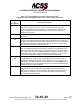
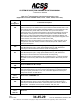
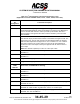
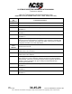
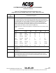
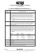
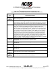
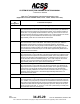
Table Of Contents
- T3CAS_Section_5
- 5 Adjustment/Test
- 1. General
- 2. Equipment
- 3. Initial Harness Checkout (New Installations Only)
- 4. System Self-Tests
- 5. Return-to-Service Test
- 6. Operational Software Loading Using an ARINC 615A Portable Data Loader or Compact Flash Card
- 7. Downloading Information from the TP3PCAS Using a CF Card
- 1. Obtain a New or Blank Compact Flash (CF) card.
- 2. Copy to the New or Blank CF card the appropriate ‘Header File’
- a) Header files are files copied to the New or Blank CF card that will instruct the computer unit what is desired to be downloaded.
- b) Header files needed to download Maintenance Data, Event Data and CRC Part Numbers can be obtained from ACSS Customer Services at +1-623-445-7070 or crc.acss@l-3com.com.
- 3. For downloading Maintenance Data, Event Data or CRC Part Numbers the aircraft does not need to be in an on-ground configuration.
- 4. Apply power to the computer unit.
- 5. Insert the CF card.
- 6. For ACSS part numbers 9005000-10000, -10101, -10202, and -10204 the DATA STATUS LED will UblinkU green once; this indicates the unit recognized that a CF card was inserted.
- 7. For ACSS part numbers 9005000-11203, -11801 and -55801 the DATA STATUS LED will UblinkU green while reading the header file and performing the action defined in the header file.
- 8. Flight Data Recording
- 1. T3CAS part numbers 9005000-10000, -10101, -10202, and -10204 only support FAT16 CF card formatting. T3CAS part numbers 9005000-11203, -11801 and -55801 support both FAT16 and FAT32 CF card formatting.
- B. Flight Data
- 1. Obtain a New or Blank CF Card.
- 2. Copy to the New or Blank CF Card the Appropriate Header File.
- 3. Header files are files copied to the New or Blank CF card that will instruct the computer unit what is desired to be downloaded.
- 4. For Flight Data Recording, the aircraft does not need to be in an on-ground configuration.
- 5. Apply power to the computer unit.
- 6. Insert the CF card.
- B. Flight Data
- 9. Downloaded Maintenance Data, Event Data And Flight Data May Be Sent To ACSS Customer Services For Analysis
- 5 Adjustment/Test
- T3CAS_Section_6
- T3CAS_Section_7
- 7 Maintenance Practices
- 1. General
- 2. Equipment and Materials
- 3. Procedure for the TP3PCAS Computer Unit
- 4. Procedure for the APM (Not applicable for part numbers 9005000-10000, -10101, -10202, -10204, or -11203)
- 5. Procedure for the Directional Antenna
- 6. Procedure for the Omnidirectional Antenna (Applicable to part numbers 9005000-11203, -11801 and -55801)
- 7. Procedure for the Control Panel
- 8. Procedure for the VSI/TRA Display
- 9. Instructions for Continued Airworthiness, FAR Part 25.1529
- 7 Maintenance Practices
- T3CAS_Section_8
- T3CAS_Section_9
- T3CAS_Section_10
- T3CAS_Appendix_A

SYSTEM DESCRIPTION AND INSTALLATION MANUAL
T
3
CAS/Part No.9005000
Table 4-1: T
3
CAS Computer Unit Interface Description (cont)
(Applicable to Part No. 9005000-10000, -10101, -10202, -10204, and -11203)
Connector
Pin
Designation
Functional Description
RMP-14D,
14E
FCU #2: Selected Altitude 701/720 ARINC 429 Bus Input
Optional TCAS input for ARINC 429 low-speed Selected Altitude labels 025 or 102.
The TCAS must also receive ARINC 429 label 204 Baro Corrected Altitude on the
XT coordination bus (either RMP-14F/G or RMP-14H/J) from the selected
transponder. Also, the selected transponder must be passing label 204 Corrected
Baro Altitude unchanged from the selected transponder’s active ARINC 429 air
data source. TCAS cannot differentiate between label 102 Selected Altitude and
label 102 GPS Vertical Dilution Of Precision (VDOP) so the system integrator must
insure that the correct label 102 is provided to the TCAS.
NOTE: These pins are designated for FCU #2 inputs if T
3
CAS is operating in full
configuration mode with TAWS, TCAS and internal transponder enabled. Else
these pins are Spares.
RMP-14F,
14G
ARINC 429 XT Coordination No.1 Input: [RMP-14F (A), RMP-14G (B)]
This differential pair input is a high-speed ARINC 429 bus (100k bits/second
nominal), that receives data from the No.1 Mode S Transponder.
RMP-14H,
14J
ARINC 429 XT Coordination No.2 Input: [RMP-14H (A), RMP-14J (B)]
This differential pair input is a high-speed ARINC 429 bus (100k bits/second
nominal), that receives data from the No.2 Mode S Transponder.
NOTE: These pins are designated for XT Coordination No.2 if T
3
CAS is operating
as TAWS and TCAS only with internal transponder disabled. Else these pins are
Spares.
RMP-14K
Traffic Selector #1 “Pull” Discrete.
RMP-15A,
15B
Reserved ARINC 429 Bus Output
RMP-15C,
15D
ARINC 429 Input: MMR/GPS #2 [RMP-15C (A), RMP-15D (B)]
This high-speed 429 input is used to receive GPS label input containing position,
velocity and quality information for the use of ADS-B IN applications and by the
transponder function for ADS-B Out.
RMP-15E
Thru
RMP-15H
Reserved for TAWS/RWS use.
RMP-15J,
15K
ARINC 429 TX Coordination No.1 Output: [RMP-15J (A), RMP-15K (B)]
This differential pair output is a high-speed ARINC 429 bus (100k bits/second
nominal), that transmits data from the T
3
CAS computer unit to the No.1 Mode S
Transponder. The labels on this bus are as follows: 273, 274, 275.
T
3
CAS Computer Unit Right Bottom Plug (RBP)
RBP-1A
Thru
RBP-1D
Reserved
4-24
04 Nov 2014
34-45-29
Pub. No. 8600200-001, Revision 004
Use or disclosure of information on this page is subject to the restrictions in the proprietary notice of this document.