
User's Manual
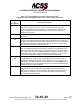
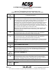
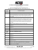
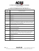
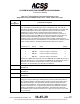
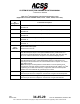
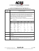
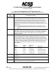
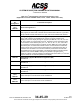
Table Of Contents
- T3CAS_Section_5
- 5 Adjustment/Test
- 1. General
- 2. Equipment
- 3. Initial Harness Checkout (New Installations Only)
- 4. System Self-Tests
- 5. Return-to-Service Test
- 6. Operational Software Loading Using an ARINC 615A Portable Data Loader or Compact Flash Card
- 7. Downloading Information from the TP3PCAS Using a CF Card
- 1. Obtain a New or Blank Compact Flash (CF) card.
- 2. Copy to the New or Blank CF card the appropriate ‘Header File’
- a) Header files are files copied to the New or Blank CF card that will instruct the computer unit what is desired to be downloaded.
- b) Header files needed to download Maintenance Data, Event Data and CRC Part Numbers can be obtained from ACSS Customer Services at +1-623-445-7070 or crc.acss@l-3com.com.
- 3. For downloading Maintenance Data, Event Data or CRC Part Numbers the aircraft does not need to be in an on-ground configuration.
- 4. Apply power to the computer unit.
- 5. Insert the CF card.
- 6. For ACSS part numbers 9005000-10000, -10101, -10202, and -10204 the DATA STATUS LED will UblinkU green once; this indicates the unit recognized that a CF card was inserted.
- 7. For ACSS part numbers 9005000-11203, -11801 and -55801 the DATA STATUS LED will UblinkU green while reading the header file and performing the action defined in the header file.
- 8. Flight Data Recording
- 1. T3CAS part numbers 9005000-10000, -10101, -10202, and -10204 only support FAT16 CF card formatting. T3CAS part numbers 9005000-11203, -11801 and -55801 support both FAT16 and FAT32 CF card formatting.
- B. Flight Data
- 1. Obtain a New or Blank CF Card.
- 2. Copy to the New or Blank CF Card the Appropriate Header File.
- 3. Header files are files copied to the New or Blank CF card that will instruct the computer unit what is desired to be downloaded.
- 4. For Flight Data Recording, the aircraft does not need to be in an on-ground configuration.
- 5. Apply power to the computer unit.
- 6. Insert the CF card.
- B. Flight Data
- 9. Downloaded Maintenance Data, Event Data And Flight Data May Be Sent To ACSS Customer Services For Analysis
- 5 Adjustment/Test
- T3CAS_Section_6
- T3CAS_Section_7
- 7 Maintenance Practices
- 1. General
- 2. Equipment and Materials
- 3. Procedure for the TP3PCAS Computer Unit
- 4. Procedure for the APM (Not applicable for part numbers 9005000-10000, -10101, -10202, -10204, or -11203)
- 5. Procedure for the Directional Antenna
- 6. Procedure for the Omnidirectional Antenna (Applicable to part numbers 9005000-11203, -11801 and -55801)
- 7. Procedure for the Control Panel
- 8. Procedure for the VSI/TRA Display
- 9. Instructions for Continued Airworthiness, FAR Part 25.1529
- 7 Maintenance Practices
- T3CAS_Section_8
- T3CAS_Section_9
- T3CAS_Section_10
- T3CAS_Appendix_A

SYSTEM DESCRIPTION AND INSTALLATION MANUAL
T
3
CAS/Part No.9005000
Table 4-1: T
3
CAS Computer Unit Interface Description (cont)
(Applicable to Part No. 9005000-10000, -10101, -10202, -10204, and -11203)
Connector
Pin
Designation
Functional Description
RMP-13F
Landing Gear Discrete Input (NO)
The T
3
CAS computer monitors this discrete that indicates the landing gear
position. Landing Gear is a Ground/Open type discrete (Note 1) where an open
indicates the gear is retracted (gear is up) and a ground indicates the gear is
extended (gear is down).
RMP-13G
Climb Inhibit No.2 Discrete Input (NO)
See RMP-1J.
RMP-13H,
13J
Radio Altimeter No.1 Input: [RMP-13H (A), RMP-13J (B)]
This input is provided for low-speed ARINC 429 (12.5k bits/s) altitude inputs from
an ARINC 707 digital radio altimeter. Radio altitude data is used for computation of
sensitivity level, inhibit descend advisories, and inhibit aural annunciation when in
close proximity to the ground. Also see RMP-2H.
RMP-13K
TCAS System Valid Discrete Output (NO)
This ground/open-type discrete output (Note 3) indicates the health status of the
T
3
CAS computer unit to other avionics systems that monitor TCAS system status.
This output is used in retrofit installations where instrumentation needs to monitor
TCAS status and the status is not available across an A429 bus. A ground at this
pin indicates normal TCAS operation. An open indicates a TCAS fault.
RMP-14A,
14B
ARINC 429 TX Coordination Bus No.2 Output: [RMP-14A (A), RMP-14B (B)]
This differential pair output is a high-speed ARINC 429 bus (100k bits/second
nominal), that transmits data from the TCAS computer unit to the No.2 Mode S
Transponder. The labels on this bus are as follows: 273, 274, 275. NOTE: These
pins are assigned to the TX Coordination Bus No.2 only if the internal transponder
is disabled. Else these pins are Spares.
RMP-14C
RA Display No.1 Status Discrete Input (NO)
This ground/open discrete input (Note 1) provides the functional status of RA
Display No.1. A ground on this pin indicates a valid display. If this discrete is not
provided by the RA display, connect to aircraft ground to prevent RA DISPLAY
No.1 fail message during self-test.
Pub. No. 8600200-001, Revision 004
34-45-29
4-23
04 Nov 2014
Use or disclosure of information on this page is subject to the restrictions in the proprietary notice of this document.