
User's Manual
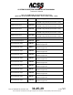
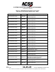
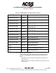
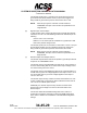
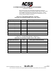
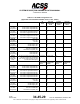

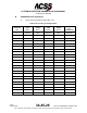
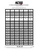
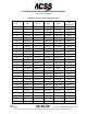
Table Of Contents
- T3CAS_Section_5
- 5 Adjustment/Test
- 1. General
- 2. Equipment
- 3. Initial Harness Checkout (New Installations Only)
- 4. System Self-Tests
- 5. Return-to-Service Test
- 6. Operational Software Loading Using an ARINC 615A Portable Data Loader or Compact Flash Card
- 7. Downloading Information from the TP3PCAS Using a CF Card
- 1. Obtain a New or Blank Compact Flash (CF) card.
- 2. Copy to the New or Blank CF card the appropriate ‘Header File’
- a) Header files are files copied to the New or Blank CF card that will instruct the computer unit what is desired to be downloaded.
- b) Header files needed to download Maintenance Data, Event Data and CRC Part Numbers can be obtained from ACSS Customer Services at +1-623-445-7070 or crc.acss@l-3com.com.
- 3. For downloading Maintenance Data, Event Data or CRC Part Numbers the aircraft does not need to be in an on-ground configuration.
- 4. Apply power to the computer unit.
- 5. Insert the CF card.
- 6. For ACSS part numbers 9005000-10000, -10101, -10202, and -10204 the DATA STATUS LED will UblinkU green once; this indicates the unit recognized that a CF card was inserted.
- 7. For ACSS part numbers 9005000-11203, -11801 and -55801 the DATA STATUS LED will UblinkU green while reading the header file and performing the action defined in the header file.
- 8. Flight Data Recording
- 1. T3CAS part numbers 9005000-10000, -10101, -10202, and -10204 only support FAT16 CF card formatting. T3CAS part numbers 9005000-11203, -11801 and -55801 support both FAT16 and FAT32 CF card formatting.
- B. Flight Data
- 1. Obtain a New or Blank CF Card.
- 2. Copy to the New or Blank CF Card the Appropriate Header File.
- 3. Header files are files copied to the New or Blank CF card that will instruct the computer unit what is desired to be downloaded.
- 4. For Flight Data Recording, the aircraft does not need to be in an on-ground configuration.
- 5. Apply power to the computer unit.
- 6. Insert the CF card.
- B. Flight Data
- 9. Downloaded Maintenance Data, Event Data And Flight Data May Be Sent To ACSS Customer Services For Analysis
- 5 Adjustment/Test
- T3CAS_Section_6
- T3CAS_Section_7
- 7 Maintenance Practices
- 1. General
- 2. Equipment and Materials
- 3. Procedure for the TP3PCAS Computer Unit
- 4. Procedure for the APM (Not applicable for part numbers 9005000-10000, -10101, -10202, -10204, or -11203)
- 5. Procedure for the Directional Antenna
- 6. Procedure for the Omnidirectional Antenna (Applicable to part numbers 9005000-11203, -11801 and -55801)
- 7. Procedure for the Control Panel
- 8. Procedure for the VSI/TRA Display
- 9. Instructions for Continued Airworthiness, FAR Part 25.1529
- 7 Maintenance Practices
- T3CAS_Section_8
- T3CAS_Section_9
- T3CAS_Section_10
- T3CAS_Appendix_A

SYSTEM DESCRIPTION AND INSTALLATION MANUAL
T
3
CAS/Part No.9005000
Table 4-17: DO-260B Configuration Pins
(Applicable to Part Numbers 9005000-11203, -11801, -55801)
RTP-13E
TAWS/XPDR
Out #4
RTP-13F
TAWS/XPDR
Out #5
RTP-13G
TAWS/XPDR
Out #6
RTP-13H
TAWS/XPDR
Out #7
RTP-9J
DO-260B
Config Data #7
ADS-B Receive Capability bit 1
VFOM Adjust bit 0
VFOM Adjust bit 1
1
0
0
1
0
1
1
1
0
1
1
1
RTP-9K
DO-260B
Config Data
Parity
NOTE: If the number of DO-260B Config
Data #1 through #7 pins connected is
even, connect RTP-9K to RTP-13B, else
RTP-9K should be left Open.
N/A
N/A
N/A
N/A
Table 4-18: DO-260B Configuration Definitions
(Applicable to Part Numbers 9005000-11203, -11801, -55801)
Length Width Code
Must be assigned the
lowest value code for
which the actual
length/width is less than
or equal to the upper
bound of the definition
0 = No Data or Unknown
1 = L – 15m, W – 23m
2 = L – 25m, W – 28.5m
3 = L – 25m, W – 34m
4 = L – 35m, W – 33m
5 = L – 35m, W – 38m
6 = L – 45m, W – 39.5m
7 = L – 45m, W – 45m
8 = L – 55m, W – 45m
9 = L – 55m, W – 52m
10 = L – 65m, W –
59.5m
11 = L – 65m, W – 67m
12 = L – 75m, W –
72.5m
13 = L – 75m, W – 80m
14 = L – 85m, W – 80m
15 = L – 85m, W – 90m
GPS Longitudinal Offset
0 = no data
1 = position offset
defined by sensor
2 = 2 meters
3 = 4
…
8 = 14 meters
31 = 60 (all values 2 and
above are (value-1)*2
meters)
VFOM Adjust
0 = VFOM adjustment of
VFOM label 136 when
using GPS MSL 076 is
NOT required
1 = VFOM adjustment of
VFOM label 136 when
using GPS MSL 076 for
geometric vertical
accuracy is required
(adds 30m to VFOM)
ADS-B Fail Disable
0 – Failures of the ADS-
B function are declared
via asserting the XPDR
fail discretes as well as
any 429 diagnostic
words
1 – Failures of the ADS-
B function are not
declared via asserting
the XPDR fail discretes,
but are declared via 429
diagnostic words
Aircraft category
0 = no info
1 = light < 15500 lbs
2 = small (15500 to
75000 lbs)
3 = large (75000 to
300000lbs)
4 = High Vortex Large
(a/c such as B-757)
5 = Heavy (>300000lbs)
6 = High Performance
(>5g acceleration and >
400knots)
7 = Rotorcraft
NACv
0 = Horizontal velocity
error Unknown or >=
10ms
1 = < 10m/s
2 = < 3 m/s
3 = < 1 m/s
ADS-B Receive Capability
0 = no support for UAT in
or 1090 in
1 = 1090 in supported
2 = 1090 AND UAT in
supported
SDA (system design
assurance)
0 = > 1x10
-3
per flight
hour
1 = <= 1x10
-3
2 = <= 1x10
-5
3 = <= 1x10
-7
Pub. No. 8600200-001, Revision 004
34-45-29
4-119
04 Nov 2014
Use or disclosure of information on this page is subject to the restrictions in the proprietary notice of this document.