
User's Manual
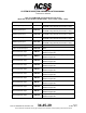
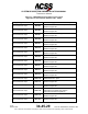
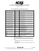
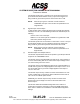
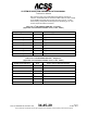
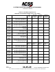

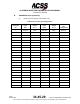
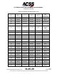
Table Of Contents
- T3CAS_Section_5
- 5 Adjustment/Test
- 1. General
- 2. Equipment
- 3. Initial Harness Checkout (New Installations Only)
- 4. System Self-Tests
- 5. Return-to-Service Test
- 6. Operational Software Loading Using an ARINC 615A Portable Data Loader or Compact Flash Card
- 7. Downloading Information from the TP3PCAS Using a CF Card
- 1. Obtain a New or Blank Compact Flash (CF) card.
- 2. Copy to the New or Blank CF card the appropriate ‘Header File’
- a) Header files are files copied to the New or Blank CF card that will instruct the computer unit what is desired to be downloaded.
- b) Header files needed to download Maintenance Data, Event Data and CRC Part Numbers can be obtained from ACSS Customer Services at +1-623-445-7070 or crc.acss@l-3com.com.
- 3. For downloading Maintenance Data, Event Data or CRC Part Numbers the aircraft does not need to be in an on-ground configuration.
- 4. Apply power to the computer unit.
- 5. Insert the CF card.
- 6. For ACSS part numbers 9005000-10000, -10101, -10202, and -10204 the DATA STATUS LED will UblinkU green once; this indicates the unit recognized that a CF card was inserted.
- 7. For ACSS part numbers 9005000-11203, -11801 and -55801 the DATA STATUS LED will UblinkU green while reading the header file and performing the action defined in the header file.
- 8. Flight Data Recording
- 1. T3CAS part numbers 9005000-10000, -10101, -10202, and -10204 only support FAT16 CF card formatting. T3CAS part numbers 9005000-11203, -11801 and -55801 support both FAT16 and FAT32 CF card formatting.
- B. Flight Data
- 1. Obtain a New or Blank CF Card.
- 2. Copy to the New or Blank CF Card the Appropriate Header File.
- 3. Header files are files copied to the New or Blank CF card that will instruct the computer unit what is desired to be downloaded.
- 4. For Flight Data Recording, the aircraft does not need to be in an on-ground configuration.
- 5. Apply power to the computer unit.
- 6. Insert the CF card.
- B. Flight Data
- 9. Downloaded Maintenance Data, Event Data And Flight Data May Be Sent To ACSS Customer Services For Analysis
- 5 Adjustment/Test
- T3CAS_Section_6
- T3CAS_Section_7
- 7 Maintenance Practices
- 1. General
- 2. Equipment and Materials
- 3. Procedure for the TP3PCAS Computer Unit
- 4. Procedure for the APM (Not applicable for part numbers 9005000-10000, -10101, -10202, -10204, or -11203)
- 5. Procedure for the Directional Antenna
- 6. Procedure for the Omnidirectional Antenna (Applicable to part numbers 9005000-11203, -11801 and -55801)
- 7. Procedure for the Control Panel
- 8. Procedure for the VSI/TRA Display
- 9. Instructions for Continued Airworthiness, FAR Part 25.1529
- 7 Maintenance Practices
- T3CAS_Section_8
- T3CAS_Section_9
- T3CAS_Section_10
- T3CAS_Appendix_A

SYSTEM DESCRIPTION AND INSTALLATION MANUAL
T
3
CAS/Part No.9005000
The discrete inputs source 1.0 ±0.25 mA of current when the input is
grounded and has diode-isolation circuitry to prevent the inputs from
being loaded to ground when power is removed from the T
3
CAS.
NOTE:
When an input goes to a discrete on both TCAS and
TAWS/RWS, the input current is twice the specification for a
single discrete.
(b) Discrete Input +28 V dc/Open
T
3
CAS provides +28 V dc/open discrete inputs for aircraft level discrete
interfaces. The +28 V dc and OPEN logic states are determined per the
following:
+28 V dc ≥14.0 V dc at the input.
OPEN ≤ 3.5 V dc at the input OR a resistance of greater than 100k
ohms to the positive voltage source.
The discrete inputs sink 1.0 ±0.25 mA of current when a +27.5 V dc input
and has diode isolation circuitry is applied to prevent the inputs from
being loaded to ground when power is removed from the T
3
CAS.
NOTE: When an input goes to a discrete on both TCAS and
TAWS/RWS, the input current is twice the specification for a
single discrete.
(c) Discrete Output Ground/Open 500 mA
The discrete outputs listed in this section pertain to ground/open discrete
outputs for the TAWS/RWS function.
The discrete output in the GROUND logic state has an output voltage of
≤3.0 V dc when sinking 500 mA of current and an output voltage of ≤1.5
V dc when sinking 100 mA of current.
The discrete output in the OPEN logic state has an output impedance of
≥ 2.4M ohms to ground for voltages applied to the output of 0.0 to +33.0
V dc and ≥100k ohms to ground for voltages applied to the output of
+33.0 to +36.0 V dc.
The discrete output circuitry contains a monitor which detects if an over-
current condition has occurred and is able to withstand a direct short to
+28 V dc for an indefinite period of time.
Additionally, the discrete output circuitry contains a monitor which
detects if the output voltage is incorrect for the driven state of the
discrete output.
This section defines the DO-260B Configuration Pins. Table 4-17
outlines the connections necessary to set the DO-260B configuration
data. Refer to Table 4-18 for definitions of the DO-260B configuration
settings.
4-116
04 Nov 2014
34-45-29
Pub. No. 8600200-001, Revision 004
Use or disclosure of information on this page is subject to the restrictions in the proprietary notice of this document.