
User's Manual
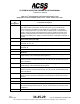
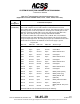
Table Of Contents
- T3CAS_Section_5
- 5 Adjustment/Test
- 1. General
- 2. Equipment
- 3. Initial Harness Checkout (New Installations Only)
- 4. System Self-Tests
- 5. Return-to-Service Test
- 6. Operational Software Loading Using an ARINC 615A Portable Data Loader or Compact Flash Card
- 7. Downloading Information from the TP3PCAS Using a CF Card
- 1. Obtain a New or Blank Compact Flash (CF) card.
- 2. Copy to the New or Blank CF card the appropriate ‘Header File’
- a) Header files are files copied to the New or Blank CF card that will instruct the computer unit what is desired to be downloaded.
- b) Header files needed to download Maintenance Data, Event Data and CRC Part Numbers can be obtained from ACSS Customer Services at +1-623-445-7070 or crc.acss@l-3com.com.
- 3. For downloading Maintenance Data, Event Data or CRC Part Numbers the aircraft does not need to be in an on-ground configuration.
- 4. Apply power to the computer unit.
- 5. Insert the CF card.
- 6. For ACSS part numbers 9005000-10000, -10101, -10202, and -10204 the DATA STATUS LED will UblinkU green once; this indicates the unit recognized that a CF card was inserted.
- 7. For ACSS part numbers 9005000-11203, -11801 and -55801 the DATA STATUS LED will UblinkU green while reading the header file and performing the action defined in the header file.
- 8. Flight Data Recording
- 1. T3CAS part numbers 9005000-10000, -10101, -10202, and -10204 only support FAT16 CF card formatting. T3CAS part numbers 9005000-11203, -11801 and -55801 support both FAT16 and FAT32 CF card formatting.
- B. Flight Data
- 1. Obtain a New or Blank CF Card.
- 2. Copy to the New or Blank CF Card the Appropriate Header File.
- 3. Header files are files copied to the New or Blank CF card that will instruct the computer unit what is desired to be downloaded.
- 4. For Flight Data Recording, the aircraft does not need to be in an on-ground configuration.
- 5. Apply power to the computer unit.
- 6. Insert the CF card.
- B. Flight Data
- 9. Downloaded Maintenance Data, Event Data And Flight Data May Be Sent To ACSS Customer Services For Analysis
- 5 Adjustment/Test
- T3CAS_Section_6
- T3CAS_Section_7
- 7 Maintenance Practices
- 1. General
- 2. Equipment and Materials
- 3. Procedure for the TP3PCAS Computer Unit
- 4. Procedure for the APM (Not applicable for part numbers 9005000-10000, -10101, -10202, -10204, or -11203)
- 5. Procedure for the Directional Antenna
- 6. Procedure for the Omnidirectional Antenna (Applicable to part numbers 9005000-11203, -11801 and -55801)
- 7. Procedure for the Control Panel
- 8. Procedure for the VSI/TRA Display
- 9. Instructions for Continued Airworthiness, FAR Part 25.1529
- 7 Maintenance Practices
- T3CAS_Section_8
- T3CAS_Section_9
- T3CAS_Section_10
- T3CAS_Appendix_A

SYSTEM DESCRIPTION AND INSTALLATION MANUAL
T
3
CAS/Part No.9005000
Table 4-1: T
3
CAS Computer Unit Interface Description (cont)
(Applicable to Part No. 9005000-10000, -10101, -10202, -10204, and -11203)
Connector
Pin
Designation
Functional Description
RMP-12D
Analog Radio Altimeter Type Select Program Input No.3 (NO)
See RMP-12B.
RMP-12E
Analog Radio Altimeter Type Select Program Input No.2 (NO)
See RMP-12B.
RMP-12F
Analog Radio Altimeter Type Select Program Input No.1 (NO)
See RMP-12B.
RMP-12G
Traffic Generator (Ethernet RX+)
The T
3
CAS computer unit may be configured in some lab installations to receive
simulated traffic over an Ethernet connection rather than RF interface. Also serves
as the A615A Dataloader Interface.
RMP-12H
Traffic Generator (Ethernet RX-)
See RMP-12G.
RMP-12J
Traffic Generator (Ethernet TX+)
The T
3
CAS computer unit may be configured in some lab installations to transmit
simulated traffic over an Ethernet connection rather than RF interface. Also serves
as the A615A Dataloader Interface.
RMP-12K
Traffic Generator (Ethernet TX-)
See RMP-12J.
RMP-13A,
13B
RA Display No.1/ARINC 429 Data Recorder Output: [RMP-13A (A), RMP-13B
(B)]
These ARINC 429 outputs are configured to output either RA information or for use
as an ARINC 429 data recorder function. The output is configured by program pin
RMP-11D. When RMP-11D is open (standard configuration), the bus is configured
for low-speed (12.5k bits/s) ARINC 429 operation and RA information is output
according to the format specified for the RA display bus in ARINC 735. When
RMP-11D is grounded, the bus is configured for high-speed (100k bits/s) ARINC
429 operation and the output supplies TA and RA information to a 429 data
recorder.
RMP-13C,
13D
RA Display No.2/ARINC 429 Data Recorder Output: [RMP-13C (A), RMP-13D
(B)]
See RMP-13A.
RMP-13E
RA Display No.2 Status Discrete Input (NO)
This ground/open discrete input (Note 1) provides the functional status of RA
Display No.2. A ground on this pin indicates a valid display. If this discrete is not
provided by the RA display, connect to aircraft ground to prevent RA DISPLAY
No.2 fail message during self-test.
4-22
04 Nov 2014
34-45-29
Pub. No. 8600200-001, Revision 004
Use or disclosure of information on this page is subject to the restrictions in the proprietary notice of this document.