
User's Manual

SYSTEM DESCRIPTION AND INSTALLATION MANUAL
T
3
CAS/Part No.9005000
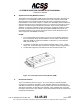
4 Data Loader Interface
The T
3
CAS is provisioned for interface with an ARINC 615A data
loader (Ethernet 10 Base-T). The front Portable Data Loader
connector contains the signals required by the ARINC 615A
specification. The interface will be used to upload future software
updates to the T
3
CAS system.
The T
3
CAS also contains an access port on the front of the unit that
accepts a Type I Compact PC Flash card. The Compact PC card is
commercially available. The Compact PC card can be inserted in a
CF card slot on a PC, or a USB serial port with an adapter. The
Compact PC Flash card is used for updating the operational
software. In addition, the Compact PC Flash card may be used as a
data recorder.
5 RS-232/Compact Flash Card Data Recorder Interface
The Data Recorder Interface can be utilized for either internal or
external data recording.
The TAWS/RWS event log contains event information due to TAWS
or windshear cautions or warnings (internal data recording). The log
can hold approximately three events that last up to 45 seconds each
(assuming GCAM Event, GCAM parameter data and GFM
parameter data selected for recording). The event log data may be
downloaded to a Laptop PC over the RS-232 port, or downloaded to
a Compact Flash card using the slot on the front of the unit.
The external data recording provides the capability to perform real-
time recording of various T
3
CAS input, output and internal data. This
data may be recorded using the Compact Flash card or RS-232
interface. Using a 2 Gigabyte Compact Flash card, the system can
store up to 15 hours of data.
In addition, the RS-232 interface allows for LRU maintenance and
troubleshooting. The maintenance log and RA event log can also be
downloaded to a PC using this port. The RS-232 interface is
connected to the 53-pin PDL connector on the front of the unit.
6 Control Panel
The control panels for the transponder and TCAS systems supply
mode control for dual or single ATC Mode S Transponders and
TCAS systems. The Control Panel for the Mode S System supplies
mode control for the ATC Transponders, both Mode S and ATCRBS
(if used). Communication with Mode S Transponders is
accomplished via an ARINC 429 bus as defined in ARINC
Characteristic 718. Control panel functions include 4096 ident code
selection and display, altitude source and reporting inhibit selection,
and selection between two onboard Transponders, TCAS TA or
TA/RA advisory selection, selection of TCAS test, and other
TCAS/XPDR related functions.
Pub. No. 8600200-001, Revision 004
34-45-29
1-55
04 Nov 2014
Use or disclosure of information on this page is subject to the restrictions in the proprietary notice of this document.