
User's Manual


SYSTEM DESCRIPTION AND INSTALLATION MANUAL
T
3
CAS/Part No.9005000
For a detailed explanation of how to activate or de-activate all of the T
3
CAS functions
using configurable and non-configurable program pins, configuration options and ASDBs,
refer to SDIM Section 4, sub-section 3 TAWS/RWS and Transponder Specifications.
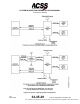
The T
3
CAS unit’s TCAS function may be installed in several different configurations
depending on the transponders used and the choice of antennas and displays. Some
typical configurations are shown in Figure 1-5. Other combinations are feasible.
Figure 1-5 shows the signals and overall interconnects for a typical T
3
CAS installation
with dual transponders.
● Configuration A shows the TCAS function using only the embedded Mode S
transponder.
● Configuration B shows the TCAS function linked to a single external transponder
Mode S transponder system as the secondary along with the embedded Mode S
transponder as the primary.
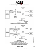
● Configuration C shows the TCAS function linked to a single external transponder
Mode S transponder system as the primary along with the embedded Mode S
transponder as the secondary.
● Configuration D shows the TCAS function linked to two external Mode S
transponders. The system may operate with either transponder depending on the
control panel selection. The second transponder acts as a backup.
Figure 1-6 illustrates a typical aircraft installation of the T
3
CAS. The system is designed
as an integrated safety solution, available as a replacement to the existing TCAS 2000,
3000, SafeRoute Surveillance Processor, or T
2
CAS LRUs. Figure 1-7 is a TCAS Function
System block diagram.
Pub. No. 8600200-001, Revision 004
34-45-29
1-41
04 Nov 2014
Use or disclosure of information on this page is subject to the restrictions in the proprietary notice of this document.