
User's Manual


SYSTEM DESCRIPTION AND INSTALLATION MANUAL
T
3
CAS/Part No.9005000
both take-off and landing approach, in order to identify the presence of a
severe low-level, downburst/microburst-type windshear.
If these wind factors cause aircraft performance to decrease to a
predetermined level, an audio warning is sounded, indicating to the crew
that the aircraft net performance capability is deteriorating and rapidly
approaching a critical state. In addition to the warning, the Windshear
Warning algorithm provides a caution when an increasing-performance
Windshear is detected, thus giving advance warning of decreasing-
performance windshear.
(f) Low RNP (Required Navigation Performance) Capability
Terrain based Low RNP (not traffic based) requires the use of a qualified
ARINC 743/743A GPS source. TAWS is capable of supporting LOW
RNP routes providing high precision lateral and vertical navigation on
airports located on mountainous regions. Please consult ACSS with
specific routes to be flown.
(g) Runway Selection Function
Applicable to part number 9005000-11203, the T
3
CAS provides
information related to the assumed landing runway on the ARINC 429
output bus. Refer to the applicable Interface Control Document (ICD) for
corresponding labels. The determination of which runway is the assumed
landing runway is based on aircraft trajectory and proximity to the
runway. The data transmitted includes information about the runway
itself (elevation, slope, landing distance available, etc.) as well as the
aircraft’s proximity to the runway threshold (lateral distance, longitudinal
distance and height above the runway). The Runway Selection outputs
from T
3
CAS are used by an aircraft-level function.
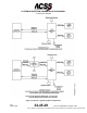
(3) Mode S Transponder Functional Description
(a) Radio Frequency (RF) Transmitter and Receiver
The T
3
CAS Mode S Data Link Transponder receives interrogations on
1030 MHz, and transmits replies to interrogations on 1090 MHz. The
transponder has antenna diversity, which means it has two RF antenna
ports connected to antennas on the top and bottom of the aircraft. When
an interrogation is received, the transponder monitors the signal on the
top and bottom antenna ports, and chooses the best port, based on
signal strength and time of arrival. The transponder then replies to the
interrogation on the port that contained the best interrogation. The
transponder contains two independent RF receiver channels, which allow
both top and bottom interrogations to be monitored simultaneously.
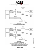
The T
3
CAS Transponder also contains data link capability, which lets it
receive COMM-A (UF=20/21) uplink messages and COMM-C (UF=24,
16 Segment) Uplink Extended Length Messages (UELM).
The T
3
CAS Transponder can transmit COMM-B (DF=20/21) downlink
messages and COMM-D (DF=24, 16 Segment) Downlink Extended
Length Messages (DELM). The transmitter has the capability of
transmitting sets of 16 segment DELMs at a rate of eight per second.
Pub. No. 8600200-001, Revision 004
34-45-29
1-35
04 Nov 2014
Use or disclosure of information on this page is subject to the restrictions in the proprietary notice of this document.