
User's Manual

SYSTEM DESCRIPTION AND INSTALLATION MANUAL
T
3
CAS/Part No.9005000
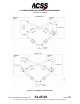
The TCAS function generates both RAs and TAs when the TA/RA mode is
selected. The two types of advisories correspond to time-based protection zones
around the aircraft. The airspace around the TCAS aircraft where an RA is
annunciated represents the warning area, while the larger airspace which results
in a TA being annunciated is the caution area. Figure 1-3 contrasts the airspace
covered by the two types of advisories.
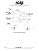
The onboard equipment listed below must be linked to the TCAS function as
shown in Figure 1-4.
● Mode S transponder with associated antennas
● Radio altimeter
● Air Data Computer (ADC) (digital or analog). If an ADC does not support
vertical speed rate data, the static line can be run directly into the Thales
VSI-TCAS.
● ATC/TCAS control panel. A separate control panel is not the only method of
control for the TCAS. Other components, such as a Radio Management Unit
(RMU) can be used.
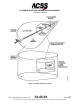
● Antenna. The TCAS function accepts two types of bottom antennas: A
standard directional antenna or an optional ATC-type omnidirectional
antenna. If an omnidirectional antenna is installed, it must be supplied by the
installer. If a directional antenna is installed at both top and bottom antenna
locations, a bottom omnidirectional antenna is not needed.
NOTE:
T
3
CAS LRU Part Numbers 9005000-10000, -10101, -10202, and -
10204 do not support a bottom omnidirectional antenna.
1-30
04 Nov 2014
34-45-29
Pub. No. 8600200-001, Revision 004
Use or disclosure of information on this page is subject to the restrictions in the proprietary notice of this document.