
User's Manual


SYSTEM DESCRIPTION AND INSTALLATION MANUAL
T
3
CAS/Part No.9005000
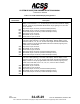
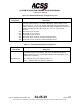
Table 1-10: ACSS VSI/TRA Display Configurations (cont.)
VSI/TRA
Part Number
Description
4067241-89X
890
891
892
893
894
895
This VSI/TRA Display provides a single range default (6.0 miles), continuous or
“POP-UP” TCAS symbology, and a test mode display. ARINC display control
features include: 6-, 12-, 14-, 20-, and 40-mile ranges and above/normal/below
display volumes. It has pin programmable VSI display (English/Metric) VSI source
selection, format mode, traffic filter, and a 1.6-, 3.2-, 5.0-, or 6.4-sec time
constants.
Gray bezel, 41-pin connector
Black bezel, 41-pin connector
Brown bezel, 41-pin connector
Gray bezel, 55-pin connector (contains bootstrap function)
Black bezel, 55-pin connector (contains bootstrap function)
Brown bezel, 55-pin connector (contains bootstrap function)
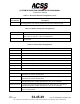
Table 1-11: Thales VSI-TCAS Display Configurations
Thales VSI-TCAS
Part Number
Description
Thales VSI-TCAS
457400XXYYYY
The Thales VSI-TCAS display provides continuous TCAS symbology and
non-ARINC display control features: mile ranges and above/normal/below
display volumes. It has pin programmable altitude band, range, lighting curve,
and VSI source selection.
XX = Hardware Version as defined in Table 1-12
YYYY = Software Version as defined in Table 1-12
Pub. No. 8600200-001, Revision 004
34-45-29
1-19
04 Nov 2014
Use or disclosure of information on this page is subject to the restrictions in the proprietary notice of this document.