
User's Manual

SYSTEM DESCRIPTION AND INSTALLATION MANUAL
T
3
CAS/Part No.9005000
Table Page
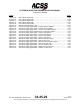
Table 4-3: Gables Control Panel Interface Descriptions ................................................................. 4-71
Table 4-4: Thales 41-Pin VSI-TCAS Interface Description ............................................................. 4-73
Table 4-5: ACSS 41-Pin VSI/TRA Interface Descriptions ............................................................... 4-79
Table 4-6: ACSS 55-Pin VSI/TRA Interface Descriptions ............................................................... 4-85
Table 4-7: Callout Configuration Items (NOTE 1) ........................................................................... 4-96
Table 4-8: Operator Selectable Options – Default Settings ............................................................ 4-97
Table 4-9: Source Destination Identifier (SDI) .............................................................................. 4-109
Table 4-10: Sign Status Matrix (SSM) (BNR) .................................................................................. 4-110
Table 4-11: Sign Status Matrix (SSM) [BCD] .................................................................................. 4-110
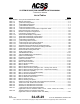
Table 4-12: APM/ASDB Programmable Discrete Inputs
(Applicable to Part Numbers 9005000-10000, -10101, -10202, -10204, -11203) ....... 4-111
Table 4-13: TAWS/XPDR Programmable Discrete Inputs
(Applicable to Part Numbers 9005000-11801, -55801) ............................................... 4-114
Table 4-14: TAWS/XPDR Programmable Discrete Outputs ........................................................... 4-115
Table 4-15: T3CAS XPDR/DO-260B SPP – Input Pins
(Applicable to Part Numbers 9005000-11203, -11801, -55801) .................................. 4-117
Table 4-16: T3CAS XPDR/DO-260B SPP – Output Pins
(Applicable to Part Numbers 9005000-11203, -11801, -55801) .................................. 4-117
Table 4-17: DO-260B Configuration Pins
(Applicable to Part Numbers 9005000-11203, -11801, -55801) .................................. 4-118
Table 4-18: DO-260B Configuration Definitions
(Applicable to Part Numbers 9005000-11203, -11801, -55801) .................................. 4-119
Table 4-19: Aircraft Type Configurations ........................................................................................ 4-120
Table 4-20: Spare Configuration/Audio Test Volume/Audio Menu Selection ................................. 4-123
Table 4-21: CRT-LCD Display Select and Alternate Lamp Format ................................................ 4-124
Table 4-22: Spare Configuration/Automatic CPA/OCPA-THD/OHD Deactivation/Spare ............... 4-125
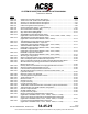
Table 4-23: Alternate Alert Priority Management/Predictive Windshear Present/
Blank Angle Function ................................................................................................... 4-126
Table 4-24: Runway Alert Function/GPS Source/Topographical Mode Function ........................... 4-127
Table 4-25: ADLP/Terr Data Comparison/Flight Function .............................................................. 4-128
Table 4-26: Lateral Position Priority/Simulator Environment .......................................................... 4-129
Table 4-27: Alternate Altitude Source Selection, Autonomous GPS Present, and
Hybrid GPS Present ..................................................................................................... 4-130
Table 4-28: Maximum Cruising True Airspeed ................................................................................ 4-131
Table 4-29: Cold Temperature Compensation Function ................................................................. 4-131
Table 4-30: Terrain Advisory Line ................................................................................................... 4-132
Table 4-31: Eleview Function .......................................................................................................... 4-132
Table 4-32: Obstacle Function ........................................................................................................ 4-133
Table 4-33: Program Pin Parity ....................................................................................................... 4-133
Table 4-34: Program Pin Parity Inputs ............................................................................................ 4-134
Table 4-35: TCAS Bottom Antenna Deactivation and XPDR Top Antenna Deactivation ............... 4-134
Table 4-36: TAWS Activation and XPDR Activation Configuration ................................................. 4-135
Table 4-37 Internal Transponder SDI ............................................................................................. 4-136
Table 4-38: ATSAW (ADS-B) Parity ................................................................................................ 4-136
Table 4-39: Program Pin Parity Inputs ............................................................................................ 4-136
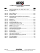
Table 4-40: Merging and Spacing Enable/Disable Configuration
(Applicable to 9005000-10000, -10101, -10202, -10204, or -11203) .......................... 4-137
Table 4-41: Surface Area Movement Management Enable/Disable Configuration
(Applicable to 9005000-10000, -10101, -10202, -10204, or -11203) .......................... 4-137
Table 4-42: In-Trail Procedures Enable/Disable Configuration
(Applicable to 9005000-10000, -10101, -10202, -10204, or -11203) .......................... 4-138
Pub. No. 8600200-001, Revision 004
34-45-29
TC-9
04 Nov 2014
Use or disclosure of information on this page is subject to the restrictions in the proprietary notice of this document.