
User's Manual

SYSTEM DESCRIPTION AND INSTALLATION MANUAL
T
3
CAS/Part No.9005000
LOADING/GRADIENT SPECIFICATIONS
1. General
This section contains the loading and gradient specifications for the input and output signals of
each component of the T
3
CAS system. The input/output discretes default to an open state when
power is removed.
2. T
3
CAS Interface Description
Refer to sub-section 3.A. TAWS/RWS/XPDR/DO-260B Data Configuration, sub-section (3)
Programmable Digital Input/Output Pins, for the definition of the physical characteristics of each
Digital signal type supported by the T
3
CAS. The T
3
CAS unit supports the following Digital signals:
ARINC 429, ARINC 453, Ethernet 10 Base-T and RS-422. Refer to Table 4-1 and Table 4-2 for
the T
3
CAS Computer Unit input and output interface definition.
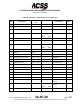
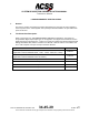
Component
Table No.
T
3
CAS Computer Unit Interface Description
(Applicable to Part No.9005000-10000, -10101, -10202, -10204, and -11203)
Table 4-1
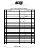
T
3
CAS Computer Unit Interface Description
(Applicable to Part No.9005000-11801 and -55801)
Table 4-2
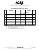
Gables Control Panel Interface Description Table 4-3
Thales 41-Pin VSI-TCAS Interface Description Table 4-4
ACSS 41-Pin VSI/TRA Interface Descriptions Table 4-5
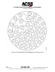
ACSS 55-Pin VSI/TRA Interface Descriptions
Table 4-6
Pub. No. 8600200-001, Revision 004
34-45-29
4-1
04 Nov 2014
Use or disclosure of information on this page is subject to the restrictions in the proprietary notice of this document.