
User's Manual

SYSTEM DESCRIPTION AND INSTALLATION MANUAL
T
3
CAS/Part No.9005000
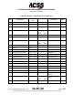
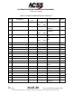
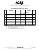
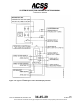
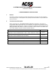
Table 3-4: ACSS 55-Pin VSI/TRA Interconnect Data (cont)
I/O Description
Connector
Pin
Connects To Notes
(I)
VS No.1 ARINC 429 (B)
J1-48 (22)
-------S--T--S----
| |
GND-- --GND
Digital ADC No.1 or
PTM No.1
2
(O)
VSI Valid Output Discrete
J1-49 (22)
----------------------
Cross--Side VSI/TRA
(O)
PTM Pwr Out (--15 V dc)
J1-50 (20)
-------S--T--S----
| |
Pressure Xdcr Mdl
3
(O)
PTM Common
J1-51 (20)
-------S--T--S----
| |
Pressure Xdcr Mdl
3
(O)
PTM Pwr Out (+15 V dc)
J1-52 (20)
-------S--T--S----
| |
GND-- --GND
Pressure Xdcr Mdl
3
Spare
J1-53
Spare
J1-54
Spare
J1-55
NOTES:
1.
Two-wire shielded cable. Tie shields to aircraft dc ground.
2.
Tie chassis ground to aircraft frame.
3.
Three-wire shielded cable. Tie shields to aircraft dc ground.
Pub. No. 8600200-001, Revision 004
34-45-29
3-21
04 Nov 2014
Use or disclosure of information on this page is subject to the restrictions in the proprietary notice of this document.