
User's Manual

SYSTEM DESCRIPTION AND INSTALLATION MANUAL
T
3
CAS/Part No.9005000
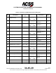
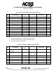
D. Control Panels
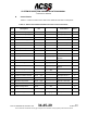
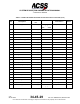
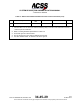
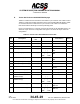
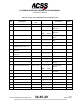
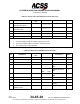
Table 3-1 contains the interconnect data for the Gables G7130 series control panels.
Table 3-1: Gables G7130-XX ATC/TCAS Control Panel Interconnect Data
I/O Description
Connector
Pin
Connects To Notes
(I)
5 V ac Panel Lighting (H)
J1-1 (20)
----------------------
Acft Lighting Source
(I)
5 V ac Panel Lighting (L)
J1-2 (20)
----------------------
Acft Lighting Source
(I)
+28 V dc Input Power (H)
J1-3 (20)
----------------------
Acft 28 V dc Supply
(I)
+28 V dc Return (L)
J1-4 (20)
----------------------
Acft dc Ground
(O)
Antenna Transfer Discrete
J1-5 (22)
----------------------
Antenna Relay
1, 2
(I)
dc Ground
J1-6 (22)
----------------------
Acft dc Ground
(O)
Standby/On Output Disc
J1-7 (22)
----------------------
Transponder No.1
(I)
Chassis Ground
J1-8 (22)
----------------------
Airframe Ground
3
(I)
Functional Test
J1-9 (22)
----------------------
Remote Test Switch
(O)
Warning & Caution
J1-10 (22)
----------------------
Remote Warn
System
2
Reserved
J1-11
(I)
XPDR Fail Logic No.2
J1-12 (22)
----------------------
Transponder No.1
(I)
Ident Input
J1-13 (22)
----------------------
Remote IDENT
Switch
2
(I)
XPDR Fail (High-Level)
J1-14
-----------NC
2, 4
(O)
Air/Gnd Switched Discrete
J1-15
-----------NC
(O)
Alt Source Select Discrete
J1-16 (22)
----------------------
Transponder No.1
2
Reserved
J1-17
(I)
Monitor Lamp Power
J1-18 (20)
----------------------
Acft 28 V dc Power
Reserved
J1-19
(I)
XPDR Configuration
J1-20
-----------NC
2
(I)
Lamp Test
J1-21 (22)
----------------------
Rmt Lamp Test SW
2
(O)
ARINC 429 (A) Out
J1-22 (22)
-------S--T--S----
| |
Transponder No.1
5
Pub. No. 8600200-001, Revision 004
34-45-29
3-11
04 Nov 2014
Use or disclosure of information on this page is subject to the restrictions in the proprietary notice of this document.