
User's Manual


SYSTEM DESCRIPTION AND INSTALLATION MANUAL
T
3
CAS/Part No.9005000
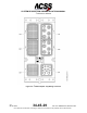
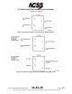
B. APM (Not applicable to 9005000-10000, -10101, -10202, -10204, or -11203.
Programming pins are used)
Figure 2-6 (Sheet 1) shows a typical APM installation. An APM can be mounted to
existing aircraft structure or can be mounted to the ACSS APM mounting bracket that is
secured to the aft side of the T
3
CAS computer tray connector (reference Figure 2-6,
Sheet 2). If the customer specifies the ACSS APM mounting bracket, the Contractor shall
manufacture and provide this APM bracket sub kit for this customer’s T
3
CAS installations.
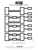
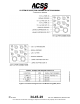
C. TCAS Antennas
The electrical installation for the TCAS antennas is specified in the LOADING AND
GRADIENT section. Figure 3-3 shows the T
3
CAS computer contact arrangement for the
top directional antenna and Figure 3-4 shows the T
3
CAS computer contact arrangement
for the bottom antenna.
3-2
04 Nov 2014
34-45-29
Pub. No. 8600200-001, Revision 004
Use or disclosure of information on this page is subject to the restrictions in the proprietary notice of this document.