
User's Manual


SYSTEM DESCRIPTION AND INSTALLATION MANUAL
T
3
CAS/Part No.9005000
than an ACSS ATC/TCAS control panel is used, refer to that particular unit’s manual for
installation data.
E. TAWS/RWS Control Panel Provisions
The TAWS controls can be mounted on a single control panel or they can be discrete
switches individually mounted at a convenient location in the Flight Deck. The TAWS
controls may be part of the electronic display menu selection in installations where TAWS
information is displayed on an EFIS or electronic display.
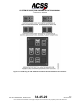
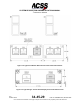
Figure 2-1 shows the ACSS King Air C90 TAWS control panel/glareshield switch
annunciator installation design. The TERR and WXR select switches shown are
momentary but alternate action switches are also supported. The terrain INHIBIT or
OVRD switches are alternate action switches and are typically guarded.
The T
3
CAS TAWS control/annunciator installation design will vary depending on the flight
deck configuration and available space.
F. VSI/TRA and VSI-TCAS Provisions
Mechanical installation data for the Thales VSI-TCAS display is shown in Figure 2-12,
and the ACSS VSI/TRA is shown in Figure 2-13. The VSI/TRA is usually used as a direct
replacement for the existing 3-ATI form VSI indicator currently mounted in the Flight
Deck. Replacement of the installation clamp may be necessary if the previous clamp is
less than 2 inches (50.8 millimeters) deep. Some older aircraft clamps do not provide
sufficient mechanical support.
If an ACSS VSI/TRA is used as the TCAS display source, and an Air Data Computer is
not available to provide vertical speed signals to the display, the installation must include
an ACSS PTM to supply air data signals to the VSI/TRA. These signals are derived from
a static pneumatic input.
If a Thales VSI-TCAS is used as the TCAS display source, and an Air Data Computer is
not available to provide vertical speed signals to the display, a static line can be run
directly into the Thales VSI-TCAS from a static pneumatic input.
G. TAWS Terrain Hazard Display Provisions
ARINC 708A and ARINC 429 WXR display and EFIS interfaces are supported. T
3
CAS
dual-independent terrain hazard display I/O supports dual ARINC 708A and dual ARINC
429 terrain hazard display systems. Figure 2-2 shows TAWS dual terrain hazard display
annunciator switch panels and locations that have been used on B757, B767, and B737-
300/400/500 aircraft. Figure 2-3 shows a typical single terrain hazard display annunciator
switch panel.
2-4
04 Nov 2014
34-45-29
Pub. No. 8600200-001, Revision 004
Use or disclosure of information on this page is subject to the restrictions in the proprietary notice of this document.