
User's Manual


SYSTEM DESCRIPTION AND INSTALLATION MANUAL
T
3
CAS/Part No.9005000
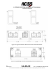
(1) Directional Antenna Installation
The directional antenna mounting and installation data is given in Figure 2-9.
Figure 2-9 contains the maximum radius dimensions for the various curved
antenna base part number units, the number of aircraft mounting holes and the
length of the connector extension for the various part number units. The antenna
must be electrically bonded (less than 5.0 milliohms bonding resistance) to the
airframe to provide a ground plane for the antenna elements.
The directional antenna must be separated by at least 30 inches (762
millimeters) from any other L-band antenna, and 60 inches (1,524 millimeters) is
preferred. If a bottom directional antenna is used, it should be the most forward
antenna on the fuselage bottom with tilt angle allowances the same as for a top-
mounted antenna.
An O-ring (included with the directional antenna) is required to be installed
between the directional antenna and the aircraft fuselage. The Navy Aeronautical
Standard part number for the O-ring is NAS 1613. The ACSS part number for the
O-ring is 4000171-240.
NOTE:
For directional antennas, ACSS Part No.7514060-90X, the customer
must provide an adapter plate for mounting to the aircraft. The antenna
base plate, to which the adapter must mate, is detailed in
Figure 2-9.
Directional antennas, ACSS Part No.7514081-9XX, come with a
preinstalled adapter plate.
NOTE:
The mounting surface of the antenna baseplate has an Alodine-treated
surface, which provides corrosion resistance. The Alodine application
material does not provide any electrical resistance or isolation. Do not
sand or remove the Alodine material from the surface. In addition,
sanding this surface may damage the unit beyond repair.
(2) Omnidirectional Antenna Installation
The omnidirectional antenna is a standard ATC-type antenna. It should be
qualified to TSO-C119 and be dc-grounded per MIL-A-90941, B-5087B. All L-
band antennas must be separated by at least 20 inches (508 millimeters). Only
one coax cable is required for installation.
The omnidirectional antenna is not supplied by ACSS. To install, follow the
manufacturer’s installation instructions.
NOTE:
The T
3
CAS part numbers 9005000-10000, -10101, -10202, and -
10204 do not support a bottom omnidirectional antenna.
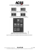
D. TCAS Control Panel Provisions
Mechanical installation data for a typical Gables GXXXX Series ATC/TCAS control panel
is shown in Figure 2-11.
It should be noted that various other types of controllers (Radio Management Units or
EFIS Display Controllers) can be used to control the TCAS display. If a controller other
Pub. No. 8600200-001, Revision 004
34-45-29
2-3
04 Nov 2014
Use or disclosure of information on this page is subject to the restrictions in the proprietary notice of this document.