
User's Manual


SYSTEM DESCRIPTION AND INSTALLATION MANUAL
T
3
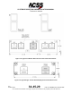
CAS/Part No.9005000
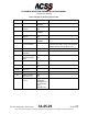
The T
3
CAS computer tray connector is RADIALL part number NSXN3P357X0001 or
equivalent. This tray connector does not come with contacts. The following contacts are
required, quantities depend on specific installation:
- 22-gauge Contact Part No. 620-200 or equivalent (wire gauges 22, 24 and 26).
- 20-gauge Contact Part No. 620-310 or equivalent (wire gauges 20, 22 and 24).
- 16-gauge Contact Part No. 620-330 or equivalent (wire gauges 18, 20, 22 and 24).
- 12-gauge Contact Part No. 620-341, or equivalent (wire gauges 18, 20, 22 and 24).
- SIZE 5 Coaxial Contact Part No. 620-021 or equivalent (Coax RG 142, RG 223 and
RG 400).
- SIZE 1 Coaxial Contact Part No. 620-119-100 or equivalent (Coax RG 225 and RG
393).
The required contacts for the LBP insert depend on if the computer is to be powered with
+28 V dc or 115 V ac and if a 115 V ac cooling fan will be connected when the computer
is powered with 115 V ac. Note that there is no output pins to support a +28 V dc cooling
fan.
B. Airplane Personality Module Provisions (Not applicable to 9005000-10000, -
10101, -10202, -10204, or -11203)
Reference Figure 2-6 for the mechanical installations of the ACSS T
3
CAS APM. The
APM can be mounted to existing aircraft structure or can be mounted to the ACSS APM
mounting bracket that is secured to the aft side of the T
3
CAS computer tray connector,
reference Figure 2-6 (Sheet 2). If the customer specifies the ACSS APM mounting
bracket, an APM bracket sub kit will be provided for the customer’s T
3
CAS installations.
NOTE:
9005000-10000, -10101, -10202, -10204, or -11203 do not require an
APM to be installed.
C. Antenna Provisions
The T
3
CAS top directional antenna should, ideally, be the most forward antenna on the
top of the aircraft and should be located as close to the longitudinal centerline as
possible. See Figure 2-7. A 5-degree tilt angle is allowed laterally, with 2-degree positive
and 5-degree negative tilt angles allowed longitudinally. See Figure 2-8.
If a bottom directional antenna is used, it should also be the most forward antenna on the
fuselage bottom. Tilt angle allowances are the same as on the top antenna. A bottom
omnidirectional antenna need not be the most forward antenna, but it should be
separated by at least 20 inches (508 millimeters) from any other L-band antenna.
Since the bottom antenna may be either a directional (standard) or an omnidirectional
(optional for part numbers 9005000-11203, -11801 and -55801) antenna, dual notation is
shown in the wiring diagram. Only one coax cable is needed for an omnidirectional
antenna installation. The bottom omnidirectional antenna and connectors must have a
loss of no greater than 2 dB for the 1030-1090 MHz range.
2-2
04 Nov 2014
34-45-29
Pub. No. 8600200-001, Revision 004
Use or disclosure of information on this page is subject to the restrictions in the proprietary notice of this document.