
User's Manual

SYSTEM DESCRIPTION AND INSTALLATION MANUAL
T
3
CAS/Part No.9005000
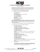
There are two fundamental differences between the uplink message and
the downlink message, as follows:
● The uplink burst is at 4 megabits per second, while the downlink is at
1 megabit per second.
● The uplink uses DPSK, while the downlink uses Pulse Position
Modulation (PPM). Using PPM, there is one pulse for every bit, either
in the first half or the second half of the bit interval (window). The first
half of the window represents a 1; the second half of the window
represents a 0.
The reply delay time for Mode S is 128 microseconds with respect to the
P6 SPR. This is true for both long and short messages. However, the
downlink message data cannot be prepared until the uplink message is
complete. There is an additional derived timing specification that
indicates how much time is available from the end of an interrogation
until the reply starts. For a short message, it is 113 microseconds; for a
long message, it is 99 microseconds. The basic Mode S transponder
handles only the short messages, but this timing shows that a data link
transponder, which handles long messages, has more data to process
and a shorter time to prepare the message.
(2) Mode S Message Format and Data Field Descriptions
Refer to RTCA DO-181C, DO-185, DO-218B and DO-260 for further details of
Mode S Message Formats and Field definitions.
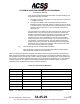
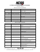
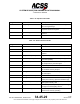
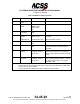
Table 1-24 defines the Mode S interrogation UF (Uplink Format) messages and Table 1-25 defines the
Mode S reply DF (Downlink Format) messages. The first 5 bits of the message indicate the UF/DF type.
The message structure including the number of bits per subfield is included in Table 1-24 and Table 1-25.
For example, UF=0 [Binary 00000] is composed of X:3 (3 bits assigned as padding), RL:1 (1 bit assigned
to Reply Length) etc. The Uplink Format message field descriptions are listed in Table 1-26 and the
Downlink Format message field descriptions are listed in Table 1-.
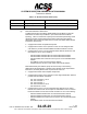
Table 1-24: Uplink Format Messages
Uplink Format
Field Description
Message Format with Number of Bits
UF=0 [00000]
Short Air-Air Surveillance
X:3, RL:1, X:4, AQ:1, DS:8, X:10 AP:24 X:Pad
UF=4 [00100]
Surveillance, Altitude Request
PC:3, RR:5, DI:3, SD:16, AP:24
UF=5 [00101]
Surveillance, Identity Request
PC:3, RR:5, DI:3, SD:16, AP:24
UF=11 [01011]
Mode S Only All-Call
PR:4, II/IC:4, CL:3, X:16, AP:24 X:Pad
UF=16 [10000]
Long Air-Air Surveillance
X:3, RL:1, X:4, AQ:1, X:18, MU:56, AP:24 X:Pad
UF=20 [10100]
Comm-A, Altitude Request
PC:3, RR:5, DI:3, SD:16, MA:56, AP:24
UF=21 [10101]
Comm-A, Identity Request
PC:3, RR:5, DI:3, SD:16, MA:56, AP:24
NOTE:
PC, RR, DI and SD subfields are undefined for UF=20/21 broadcast interrogations.
Pub. No. 8600200-001, Revision 004
34-45-29
1-116
04 Nov 2014
Use or disclosure of information on this page is subject to the restrictions in the proprietary notice of this document.