
User's Manual

SYSTEM DESCRIPTION AND INSTALLATION MANUAL
T
3
CAS/Part No.9005000
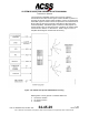
Inside the P6 pulse, the first phase change occurs 1.25
microseconds into the pulse. This phase change is called the Sync
Phase Reversal (SPR), and it is used to synchronize the transponder
with the ground station. The SPR is used as the timing reference for
the Mode S reply for uplink messages. Response time is 128 ±0.25
microseconds.
All t he p ossible phase c hanges ( chips), c orresponding t o t he d ata
bits, ar e i nside the P6 pulse a nd oc cur af ter t he SPR. Since the
uplink message c onsists of 4 megabits per s econd, it m eans t hat
there i s a pos sible phase c hange (chip) ev ery 0. 25 m icroseconds.
This pr ocess i s c alled D ifferential P hase Shift K eying ( DPSK). If
there i s a one in the da ta stream, t he phas e c hanges. H owever, i f
there is a zero in the data stream, it does not change.
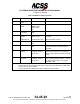
All of the short 56-bit Mode S uplink messages have the following two
things in common:
● The first five bits are always the Uplink Format (UF) number. For
example, in a UF = 0, the first five bits are all zero (00000); in a UF =
4, the first five bits are 00100. Downlink messages are identified by
the abbreviation DF for Downlink Format.
● The last 24 bits are an address/parity field. This is a means of
addressing the uplink message (interrogation) and it is also a means
of error detection. The last 24 bits do not carry data, but rather the
unique address of the aircraft overlaid with the parity bits. A CRC
system is actually used for the entire uplink message. The
transponder starts to handle the uplink message only when it
ensures that the message is intended for the aircraft in which the
transponder is installed.
The uplink message can be a broadcast-type message intended for
all aircraft in range of the ground station. This is the Mode S-only All-
Call message, which is a special format (UF = 11) that contains an
all-ones address. Mode S SLS is handled by a P5 pulse, which has a
pulse width of 0.8 microseconds. P5 is transmitted simultaneously
with the P6 Sync Phase Reversal (SPR); the P5 pulse subsequently
covers the SPR. When this occurs, the decoder in the receiver
cannot see the SPR and, therefore, does not process the uplink
message. This decoding procedure is different from the ATCRBS
method where the amplitude of the P2 pulse must actually be
detected for SLS. The Mode S reply is then generated either in
response to a Mode S interrogation or by one of the ATCRBS/Mode
S All-Calls. The reply includes a preamble made up of two pairs of
pulses that occur 8 microseconds before the first Mode S downlink
pulse. The preamble precedes the actual data on the downlink
message, much like the P1, P2, and P6 pulses precede the uplink
message.
Pub. No. 8600200-001, Revision 004
34-45-29
1-115
04 Nov 2014
Use or disclosure of information on this page is subject to the restrictions in the proprietary notice of this document.