
User's Manual

SYSTEM DESCRIPTION AND INSTALLATION MANUAL
T
3
CAS/Part No.9005000
● Radio Altitude
(6) TAWS Display Symbology
The terrain hazard display function generates an image that provides the
following information to the flight crew:
● A Terrain Display Background consisting of shaded areas representing
terrain at different altitudes relative to the aircraft altitude.
● A Terrain Advisory Line depicting the point or points where a CPA caution
will occur if the aircraft continues on its current trajectory.
● Terrain Alert areas corresponding to the terrain that is causing a CPA caution
or warning.Each of these features is explained in the following sub-sections.
NOTE:
Obstacles will not generate the Terrain Advisory Line.
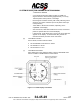
(a) Terrain Display Background
The purpose of the Terrain Display Background is to provide overall
situational awareness to the crew about the relative height of the terrain
near the aircraft.
The terrain is divided into “slices” based on the elevation of the terrain
with respect to an aircraft reference altitude. Slices above or very near
the reference altitude are typically shown as varying shades of yellow.
Slices safely below the reference altitude are typically shown as varying
shades of green or even black.
The reference altitude is a surface starting at the aircraft and propagating
forward along the aircraft flight path angle for 30 seconds. The reference
altitude surface then extends horizontally at the altitude the aircraft is
expected to have at that time (i.e., 30 seconds in the future).
The specific colors and textures used for the various slices, as well as
the threshold altitudes for the slices, are contained in the Aircraft Specific
Database (ASDB) and thus can be tailored for specific installations.
Figure 1-25 shows a typical color scheme and altitude definitions. (Note:
The figure is drawn in color. If this document is printed in black and
white, the different yellow and green textures representing different
terrain elevations will appear as different shades of gray.)
NOTE:
For Part Numbers 9005000-10000, -10101, -10202, -10204, -
11203, -11801 and -55801, in order to comply with the dark
cockpit philosophy and to avoid covering up symbols
displayed by other systems (FMS maps, trajectories, TCAS
intruders) the non alerting areas are black.
For Part Numbers 9005000-10000, -10101, -10202, -10204, -11203, -
11801 and -55801 the terrain colored textures is as follows:
Slice 1 - Black
Slice 2 - Light Density Green (12.5% dot density)
Slice 3 - Medium Density Green (25% dot density)
Pub. No. 8600200-001, Revision 004
34-45-29
1-93
04 Nov 2014
Use or disclosure of information on this page is subject to the restrictions in the proprietary notice of this document.