
User's Manual

SYSTEM DESCRIPTION AND INSTALLATION MANUAL
T
3
CAS/Part No.9005000
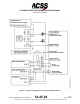
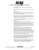
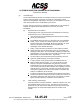
Figure 1-15: ACSS VSI/TRA Interface Diagram (55-Pin Version)
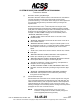
G. TAWS Terrain Hazard Display
T
3
CAS installations require at least one TAWS terrain hazard display. ARINC 708A WXR
display and EFIS interfaces are supported. Figure 1-16 shows a typical single ARINC
708A terrain hazard display interface. The T
3
CAS dual-independent terrain hazard
display I/O supports dual ARINC 708A terrain hazard display systems. The terrain image
is transmitted via 453 bus to the display.
(1) Functional Description and Operation
The terrain hazard display function enhances situational awareness by providing
a display of terrain-related hazardous situations in front of the aircraft on existing
ARINC 708A-compatible weather radar or EFIS flight deck displays. The display
may be either the EFIS Navigation Display (for EFIS-equipped aircraft) or the
weather radar display. A crew-activated switch is used to select/deselect the
terrain image on the display.
Pub. No. 8600200-001, Revision 004
34-45-29
1-75
04 Nov 2014
Use or disclosure of information on this page is subject to the restrictions in the proprietary notice of this document.