
User's Manual


SYSTEM DESCRIPTION AND INSTALLATION MANUAL
T
3
CAS/Part No.9005000
Bootstrapping of vertical speed inputs as currently implemented on L-1011,
A300, A310, and A300-600 aircraft, is provided with a larger ACSS 55-pin unit
connector. These units have a unique dash number assigned to them.
Table 1-20: ACSS VSI/TRA Leading Particulars
Item
Specification
Dimensions (maximum)
●
Height
3.26 in. (82.8 mm)
● Width 3.26 in. (82.8 mm)
●
Length
9.42 in. (239.3 mm)
Weight (maximum)
4.0 lb (1.81 kg)
Power Requirements:
●
Primary
115 V, 400 Hz; 18 W nominal,
31 W maximum
●
External Circuit Breaker Rating
1 A at 115 V ac
Display Type
LCD
Mating Connectors:
● J1 (41 Pin Version) M83723/75A-20-41N
●
J1 (55 Pin Version)
M83723/75A-22-55N
Mounting
3-ATI Clamp, Marmon NH1004994-30
or MSP 64311B
Environmental Specifications (DO-160B)
(A2F1)AKXXXXXXAEAEZZZK
Various dash number VSI/TRA displays are available that provide unique design
characteristics, which include VSI rate filter programming and selection of an
English or metric rate scale.
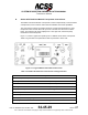
The VSI/TRA also displays symbology corresponding to traffic in the vicinity of
the aircraft. Threat information is received from the TCAS function on a dedicated
high-speed ARINC 429 bus. The display uses the bearing, altitude, and range
data for each threat to provide an indication of the proximity of the threat.
Allowable (non-illuminated or green illuminated bands) and prohibited (red
illuminated bands) vertical rates are displayed based on information received
from the TCAS function. The VSI/TRA can be pin programmed to provide vertical
speed data only, vertical speed and resolution advisory data, or vertical speed,
resolution advisory and traffic advisory data. Display of the TCAS system fault
status is provided on the VSI/TRA in response to extended TCAS control panel
TEST activation.
Pub. No. 8600200-001, Revision 004
34-45-29
1-71
04 Nov 2014
Use or disclosure of information on this page is subject to the restrictions in the proprietary notice of this document.